OBD2 end avatud & laiendada kaabel kontaktide paigutus ,Palun kliki Siin
Standard OBD2 Pinout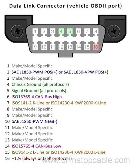
Soure:wiki
Režiimid
On 10 kirjeldatud OBD-II Viimane standard SAE J1979 töötamiseks. Need on järgmised:
| Režiim (Hex) | Kirjeldus |
|---|---|
| 01 | Saate kuvada praeguse andmed |
| 02 | Näita freeze frame data |
| 03 | Näita salvestatud diagnostilised veakoodid |
| 04 | Selge diagnostilised veakoodid ja salvestatud väärtused |
| 05 | Testi tulemused, hapniku sensor seire (Mittesuitsetajate on võimalik) |
| 06 | Testi tulemused, muu osa/süsteemi jälgimine (Testi tulemused, hapniku anduri saab üksnes järelevalve) |
| 07 | Näita ootel diagnostilised veakoodid (praeguse või viimase sõidutsükkel avastatud) |
| 08 | Rongisisene osa/süsteemi toimimise kontrolli |
| 09 | Taotleda sõidukite |
| 0A | Püsiva Diagnostilised veakoodid (Tml) (Puhastatud tml) |
Sõidukitootjad ei nõutaks kõigi transpordiliikide. Iga tootja võib kindlaks määrata täiendavad režiimid eespool #9 (nt: režiim 22 Ford/GM SAE J2190 määratletud, režiim 21 Toyota) muud teavet nt jaoks. veojõu aku pinge on hübriidelektrisõiduk (HEV).[2]
Standard PID
Järgmine tabel näitab OBD-II standard PID SAE J1979 määratletud. Eeldatav vastus iga PID antakse, Kuidas tõlkida vastuse usaldusväärsed andmed koos. Uuesti, Kõik sõidukid toetab kõiki PID ja ei saa olla tootja määratletud kohandatud PID, mis on määratletud standardi OBD-II.
Märkus et režiimid 1 ja 2 on põhimõtteliselt identsed, välja arvatud sellisele 1 Praegune teave, arvestades, et režiimis 2 annab tehtud asi kui viimati diagnostika kood loodi andmete hetktõmmis. Erandiks on PID 01, mis on ainult režiimis saadaval 1, ja PID 02, mis on ainult režiimis saadaval 2. Kui režiim 2 PID 02 Tagastab nulli, siis ei ole hetktõmmis ja muu režiimi 2 andmed on mõttetu.
Bit-kodeeritud märke kasutades, kogused nagu C4 tähendab bit 4 andmed baitide C:. Iga natuke numerated: 0 et 7, nii 7 bitt on ja 0 bitt on.
| A | B | C | D | ||||||||||||||||||||||||||||
| A7 | A6 | A5 | A4 | A3 | A2 | A1 | A0 | B7 | B6 | B5 | B4 | B3 | B2 | B1 | B0 | C7 | C6 | C5 | C4 | C3 | C2 | C1 | C0 | D7 | D6 | D5 | D4 | D3 | D2 | D1 | D0 |
Režiim 01
| PID (Hex) |
PID (Dets) |
Tagastatud baiti andmeid | Kirjeldus | Min väärtus | Max väärtus | Üksused | Valem[a] |
|---|---|---|---|---|---|---|---|
| 00 | 0 | 4 | PID toetatud [01 – 20] | Kodeeritud bit [A7. D0] == [PID $01.. PID $20] Vt allpool | |||
| 01 | 1 | 4 | Monitor staatus pärast tml tühjendatud. (Sisaldab rikke märgutuli (MIL) ning tml arvu.) | Kodeeritud bit. Vt allpool | |||
| 02 | 2 | 2 | Külmutada DTC | ||||
| 03 | 3 | 2 | Kütuse süsteemi olek | Kodeeritud bit. Vt allpool | |||
| 04 | 4 | 1 | Arvutatud mootori koormus | 0 | 100 | % | {\displaystyle {\tfrac {100}{255}}A} (või {\displaystyle {\tfrac {A}{2.55}}}) |
| 05 | 5 | 1 | Mootori jahutusvedeliku temperatuur | -40 | 215 | ° C | {\displaystyle A-40} |
| 06 | 6 | 1 | Lühikese aja jooksul kütuse doseerimise — panga 1 | -100 (Vähendada kütuse: Liiga rikas) | 99.2 (Lisada kütust: Liiga lahja) | % |
{\displaystyle {\jaoks {100}{128}}A-100}
(või {\displaystyle {\tfrac {A}{1.28}}-100} ) |
| 07 | 7 | 1 | Pikaajaline kütuse doseerimine-Pank 1 | ||||
| 08 | 8 | 1 | Lühikese aja jooksul kütuse doseerimise — panga 2 | ||||
| 09 | 9 | 1 | Pikaajaline kütuse doseerimine-Pank 2 | ||||
| 0A | 10 | 1 | Kütuse rõhk (ülerõhk) | 0 | 765 | kPa | {\displaystyle 3A} |
| 0B | 11 | 1 | Sisselasketorustiku absoluutne surve | 0 | 255 | kPa | {\displaystyle A} |
| 0C | 12 | 2 | Mootori p/min | 0 | 16,383.75 | p/min | {\displaystyle {\jaoks {256A + B}{4}}} |
| 0D | 13 | 1 | Sõiduki kiirus | 0 | 255 | km/h | {\displaystyle A} |
| 0E | 14 | 1 | Ajastus ette | -64 | 63.5 | ° enne TDC | {\displaystyle {\jaoks {A}{2}}-64} |
| 0F | 15 | 1 | Siseneva õhuvoolu temperatuuri | -40 | 215 | ° C | {\displaystyle A-40} |
| 10 | 16 | 2 | MAF kulu | 0 | 655.35 | g/s | {\displaystyle {\jaoks {256A + B}{100}}} |
| 11 | 17 | 1 | Seguklapp | 0 | 100 | % | {\displaystyle {\tfrac {100}{255}}A} |
| 12 | 18 | 1 | Käskis teisese õhu seisund | Kodeeritud bit. Vt allpool | |||
| 13 | 19 | 1 | Oxygen Sensor käesoleva (aastal 2 pangad) | [A0. A3] == Pank 1, Andurid 1-4. [A4... A7] == Pank 2… | |||
| 14 | 20 | 2 | Hapniku Sensor 1 A: Pinge B: Lühiajaline kütuse doseerimise |
0 -100 |
1.275 99.2 |
v % |
{\displaystyle {\jaoks {A}{200}}}
{\displaystyle {\jaoks {100}{128}}B-100}
(Kui B == $FF, andur ei kasutata trimmi arvutamine) |
| 15 | 21 | 2 | Hapniku Sensor 2 A: Pinge B: Lühiajaline kütuse doseerimise |
||||
| 16 | 22 | 2 | Hapniku Sensor 3 A: Pinge B: Lühiajaline kütuse doseerimise |
||||
| 17 | 23 | 2 | Hapniku Sensor 4 A: Pinge B: Lühiajaline kütuse doseerimise |
||||
| 18 | 24 | 2 | Hapniku Sensor 5 A: Pinge B: Lühiajaline kütuse doseerimise |
||||
| 19 | 25 | 2 | Hapniku Sensor 6 A: Pinge B: Lühiajaline kütuse doseerimise |
||||
| 1A | 26 | 2 | Hapniku Sensor 7 A: Pinge B: Lühiajaline kütuse doseerimise |
||||
| 1B | 27 | 2 | Hapniku Sensor 8 A: Pinge B: Lühiajaline kütuse doseerimise |
||||
| 1C | 28 | 1 | Sõiduk vastab OBD standardid | Kodeeritud bit. Vt allpool | |||
| 1D | 29 | 1 | Oxygen Sensor käesoleva (aastal 4 pangad) | Sarnane PID 13, Aga [A0. A7] == [B1S1, B1S2, B2S1, B2S2, B3S1, B3S2, B4S1, B4S2] | |||
| 1E | 30 | 1 | Abistava sisendi olek | A0 == Võimu startida (PTO) olek (1 == aktiivne) [A1. A7] kasutamata |
|||
| 1F | 31 | 2 | Kuna mootor käivitu Käitusaeg | 0 | 65,535 | sekundit | {\displaystyle 256A + B} |
| 20 | 32 | 4 | PID toetatud [21 – 40] | Kodeeritud bit [A7. D0] == [PID $21.. PID $40] Vt allpool | |||
| 21 | 33 | 2 | Läbitud teepikkuse rikke märgutuli (MIL) kohta | 0 | 65,535 | km | {\displaystyle 256A + B} |
| 22 | 34 | 2 | Kütuse raudtee Surve (võrreldes sisselasketorustiku rõhku) | 0 | 5177.265 | kPa | {\displaystyle 0.079(256A + B)} |
| 23 | 35 | 2 | Kütuse raudtee Siserõhu (diisel, või bensiini otsesissepritse) | 0 | 655,350 | kPa | {\displaystyle 10(256A + B)} |
| 24 | 36 | 4 | Hapniku Sensor 1 AB: Kütuse-õhu samaväärsuse suhe CD: Pinge |
0 0 |
< 2 < 8 |
suhe V |
{\displaystyle {\jaoks {2}{65536}}(256A + B)}
{\displaystyle {\jaoks {8}{65536}}(256C + D)}
|
| 25 | 37 | 4 | Hapniku Sensor 2 AB: Kütuse-õhu samaväärsuse suhe CD: Pinge |
||||
| 26 | 38 | 4 | Hapniku Sensor 3 AB: Kütuse-õhu samaväärsuse suhe CD: Pinge |
||||
| 27 | 39 | 4 | Hapniku Sensor 4 AB: Kütuse-õhu samaväärsuse suhe CD: Pinge |
||||
| 28 | 40 | 4 | Hapniku Sensor 5 AB: Kütuse-õhu samaväärsuse suhe CD: Pinge |
||||
| 29 | 41 | 4 | Hapniku Sensor 6 AB: Kütuse-õhu samaväärsuse suhe CD: Pinge |
||||
| 2A | 42 | 4 | Hapniku Sensor 7 AB: Kütuse-õhu samaväärsuse suhe CD: Pinge |
||||
| 2B | 43 | 4 | Hapniku Sensor 8 AB: Kütuse-õhu samaväärsuse suhe CD: Pinge |
||||
| 2C | 44 | 1 | Käskis EGR | 0 | 100 | % | {\displaystyle {\tfrac {100}{255}}A} |
| 2D | 45 | 1 | EGR viga | -100 | 99.2 | % | {\displaystyle {\tfrac {100}{128}}A-100} |
| 2E | 46 | 1 | Käskis kütuseaurude purge | 0 | 100 | % | {\displaystyle {\tfrac {100}{255}}A} |
| 2F | 47 | 1 | Kütusepaagi taseme sisend | 0 | 100 | % | {\displaystyle {\tfrac {100}{255}}A} |
| 30 | 48 | 1 | Sooja-ups, sest koodid kustutatud | 0 | 255 | arv | {\displaystyle A} |
| 31 | 49 | 2 | Läbitud Kuna koodid kustutatud | 0 | 65,535 | km | {\displaystyle 256A + B} |
| 32 | 50 | 2 | Evap. Süsteemi küllastunud auru rõhk | -8,192 | 8191.75 | PA | {\displaystyle {\jaoks {256A + B}{4}}}(AB on kaks 's täiendab allkirjastatud)[3] |
| 33 | 51 | 1 | Absoluutne õhurõhk | 0 | 255 | kPa | {\displaystyle A} |
| 34 | 52 | 4 | Hapniku Sensor 1 AB: Kütuse-õhu samaväärsuse suhe CD: Hoovus |
0 -128 |
< 2 <128 |
suhe mA |
{\displaystyle {\jaoks {2}{65536}}(256A + B)}
{\displaystyle {\jaoks {256C + D}{256}}-128}
või {\displaystyle C +{\jaoks {D}{256}}-128} |
| 35 | 53 | 4 | Hapniku Sensor 2 AB: Kütuse-õhu samaväärsuse suhe CD: Hoovus |
||||
| 36 | 54 | 4 | Hapniku Sensor 3 AB: Kütuse-õhu samaväärsuse suhe CD: Hoovus |
||||
| 37 | 55 | 4 | Hapniku Sensor 4 AB: Kütuse-õhu samaväärsuse suhe CD: Hoovus |
||||
| 38 | 56 | 4 | Hapniku Sensor 5 AB: Kütuse-õhu samaväärsuse suhe CD: Hoovus |
||||
| 39 | 57 | 4 | Hapniku Sensor 6 AB: Kütuse-õhu samaväärsuse suhe CD: Hoovus |
||||
| 3A | 58 | 4 | Hapniku Sensor 7 AB: Kütuse-õhu samaväärsuse suhe CD: Hoovus |
||||
| 3B | 59 | 4 | Hapniku Sensor 8 AB: Kütuse-õhu samaväärsuse suhe CD: Hoovus |
||||
| 3C | 60 | 2 | Katalüsaatori temperatuur: Pank 1, Andur 1 | -40 | 6,513.5 | ° C | {\displaystyle {\jaoks {256A + B}{10}}-40} |
| 3D | 61 | 2 | Katalüsaatori temperatuur: Pank 2, Andur 1 | ||||
| 3E | 62 | 2 | Katalüsaatori temperatuur: Pank 1, Andur 2 | ||||
| 3F | 63 | 2 | Katalüsaatori temperatuur: Pank 2, Andur 2 | ||||
| 40 | 64 | 4 | PID toetatud [41 – 60] | Kodeeritud bit [A7. D0] == [PID $41.. PID $60] Vt allpool | |||
| 41 | 65 | 4 | Monitor staatus selle draivi tsükli | Kodeeritud bit. Vt allpool | |||
| 42 | 66 | 2 | Moodul pinget | 0 | 65.535 | V | {\displaystyle {\jaoks {256A + B}{1000}}} |
| 43 | 67 | 2 | Absoluutne koormus | 0 | 25,700 | % | {\displaystyle {\tfrac {100}{255}}(256A + B)} |
| 44 | 68 | 2 | Kütuse-õhu käskis samaväärsuse suhe | 0 | < 2 | suhe | {\displaystyle {\tfrac {2}{65536}}(256A + B)} |
| 45 | 69 | 1 | Suhteline seguklapp | 0 | 100 | % | {\displaystyle {\tfrac {100}{255}}A} |
| 46 | 70 | 1 | Välisõhu temperatuur | -40 | 215 | ° C | {\displaystyle A-40} |
| 47 | 71 | 1 | Absoluutne seguklapp B | 0 | 100 | % | {\displaystyle {\jaoks {100}{255}}A} |
| 48 | 72 | 1 | Absoluutne seguklapp C | ||||
| 49 | 73 | 1 | Gaasi pedaali asend D | ||||
| 4A | 74 | 1 | Gaasi pedaali asend E | ||||
| 4B | 75 | 1 | Gaasi pedaali asend F | ||||
| 4C | 76 | 1 | Käskis seguklapi ajami | ||||
| 4D | 77 | 2 | Aeg, MIL koos sõitma | 0 | 65,535 | minutit | {\displaystyle 256A + B} |
| 4E | 78 | 2 | Aega, sest veakoodid tühjendatud | ||||
| 4F | 79 | 4 | Kütuse-õhu suhe samaväärsuse maksimumväärtus, hapniku anduri pinge, Hapnikuandur praeguse, ja sisselasketorustiku absoluutne surve | 0, 0, 0, 0 | 255, 255, 255, 2550 | suhe, V, mA, kPa | A, B, C, D * 10 |
| 50 | 80 | 4 | Õhu voolukiirus mass air flow sensor maksimumväärtus | 0 | 2550 | g/s | A * 10, B, C, ja D on reserveeritud kasutamiseks tulevikus |
| 51 | 81 | 1 | Kütuse liik | Kütuse tüüp tabelist vt allpool | |||
| 52 | 82 | 1 | Etanooli kütuse % | 0 | 100 | % | {\displaystyle {\tfrac {100}{255}}A} |
| 53 | 83 | 2 | Absoluutne Evap süsteemi küllastunud auru rõhk | 0 | 327.675 | kPa | {\displaystyle {\jaoks {256A + B}{200}}} |
| 54 | 84 | 2 | Evap süsteemi küllastunud auru rõhk | -32,767 | 32,768 | PA | ((A * 256)+B)-32767 |
| 55 | 85 | 2 | Lühiajaline teisese Hapnikuandur trimmi, A: Pank 1, B: Pank 3 | -100 | 99.2 | % | {\displaystyle {\jaoks {100}{128}}A-100}{\displaystyle {\jaoks {100}{128}}B-100} |
| 56 | 86 | 2 | Kaua mõiste sekundaarne Hapnikuandur trimmi, A: Pank 1, B: Pank 3 | ||||
| 57 | 87 | 2 | Lühiajaline teisese Hapnikuandur trimmi, A: Pank 2, B: Pank 4 | ||||
| 58 | 88 | 2 | Kaua mõiste sekundaarne Hapnikuandur trimmi, A: Pank 2, B: Pank 4 | ||||
| 59 | 89 | 2 | Kütuse raudtee absoluutse rõhu | 0 | 655,350 | kPa | {\displaystyle 10(256A + B)} |
| 5A | 90 | 1 | Suhteline gaasi pedaali asend | 0 | 100 | % | {\displaystyle {\tfrac {100}{255}}A} |
| 5B | 91 | 1 | Hübriid aku järelejäänud eluea | 0 | 100 | % | {\displaystyle {\tfrac {100}{255}}A} |
| 5C | 92 | 1 | Mootoriõli temperatuur | -40 | 210 | ° C | {\displaystyle A-40} |
| 5D | 93 | 2 | Sissepritse ajastus | -210.00 | 301.992 | ° | {\displaystyle {\jaoks {256A + B}{128}}-210} |
| 5E | 94 | 2 | Mootori kütuse määr | 0 | 3276.75 | L/h | {\displaystyle {\jaoks {256A + B}{20}}} |
| 5F | 95 | 1 | Heitenõuded, kuhu sõiduk on konstrueeritud | Kodeeritud bit | |||
| 60 | 96 | 4 | PID toetatud [61 – 80] | Kodeeritud bit [A7. D0] == [PID $61.. PID $80] Vt allpool | |||
| 61 | 97 | 1 | Juhi nõudluse mootor – pöördemomendi | -125 | 125 | % | 125 |
| 62 | 98 | 1 | Tegelik mootori – pöördemomendi | -125 | 125 | % | 125 |
| 63 | 99 | 2 | Viide Max pöördemoment | 0 | 65,535 | Nm | {\displaystyle 256A + B} |
| 64 | 100 | 5 | Mootori pöördemomendi andmed | -125 | 125 | % | 125 jõude B-125 mootori punkti 1 C-125 mootori punkti 2 D-125 mootori punkti 3 E-125 mootori punkti 4 |
| 65 | 101 | 2 | Aux sisendi / toetatud väljund | Kodeeritud bit | |||
| 66 | 102 | 5 | Mass air flow sensor | ||||
| 67 | 103 | 3 | Mootori jahutusvedeliku temperatuur | ||||
| 68 | 104 | 7 | Sisselaskeõhu temperatuuri andur | ||||
| 69 | 105 | 7 | Käskis EGR ja EGR viga | ||||
| 6A | 106 | 5 | Commanded Diesel intake air flow control and relative intake air flow position | ||||
| 6B | 107 | 5 | Exhaust gas recirculation temperature | ||||
| 6C | 108 | 5 | Commanded throttle actuator control and relative throttle position | ||||
| 6D | 109 | 6 | Fuel pressure control system | ||||
| 6E | 110 | 5 | Injection pressure control system | ||||
| 6F | 111 | 3 | Turbocharger compressor inlet pressure | ||||
| 70 | 112 | 9 | Boost pressure control | ||||
| 71 | 113 | 5 | Variable Geometry turbo (VGT) control | ||||
| 72 | 114 | 5 | Wastegate control | ||||
| 73 | 115 | 5 | Exhaust pressure | ||||
| 74 | 116 | 5 | Turbocharger RPM | ||||
| 75 | 117 | 7 | Turbocharger temperature | ||||
| 76 | 118 | 7 | Turbocharger temperature | ||||
| 77 | 119 | 5 | Charge air cooler temperature (CACT) | ||||
| 78 | 120 | 9 | Exhaust Gas temperature (EGT) Pank 1 | Special PID. Vt allpool | |||
| 79 | 121 | 9 | Exhaust Gas temperature (EGT) Pank 2 | Special PID. Vt allpool | |||
| 7A | 122 | 7 | Diesel particulate filter (DPF) | ||||
| 7B | 123 | 7 | Diesel particulate filter (DPF) | ||||
| 7C | 124 | 9 | Diesel Particulate filter (DPF) temperature | ||||
| 7D | 125 | 1 | NOx NTE (Not-To-Exceed) control area status | ||||
| 7E | 126 | 1 | PM NTE (Not-To-Exceed) control area status | ||||
| 7F | 127 | 13 | Engine run time | ||||
| 80 | 128 | 4 | PID toetatud [81 – A0] | Kodeeritud bit [A7. D0] == [PID $81..PID $A0] Vt allpool | |||
| 81 | 129 | 21 | Engine run time for Auxiliary Emissions Control Device(AECD) | ||||
| 82 | 130 | 21 | Engine run time for Auxiliary Emissions Control Device(AECD) | ||||
| 83 | 131 | 5 | NOx sensor | ||||
| 84 | 132 | Manifold surface temperature | |||||
| 85 | 133 | NOx reagent system | |||||
| 86 | 134 | Particulate matter (PM) sensor | |||||
| 87 | 135 | Sisselasketorustiku absoluutne surve | |||||
| A0 | 160 | 4 | PID toetatud [A1 – C0] | Kodeeritud bit [A7. D0] == [PID $A1..PID $C0] Vt allpool | |||
| C0 | 192 | 4 | PID toetatud [C1 – E0] | Kodeeritud bit [A7. D0] == [PID $C1..PID $E0] Vt allpool | |||
| C3 | 195 | ? | ? | ? | ? | ? | Returns numerous data, including Drive Condition ID and Engine Speed* |
| C4 | 196 | ? | ? | ? | ? | ? | B5 is Engine Idle Request B6 is Engine Stop Request* |
| PID (Hex) |
PID (Dets) |
Tagastatud baiti andmeid | Kirjeldus | Min väärtus | Max väärtus | Üksused | Valem[a] |


Režiim 02[edit]
Režiim 02 accepts the same PIDs as mode 01, with the same meaning, but information given is from when the freeze frame was created.
You have to send the frame number in the data section of the message.
| PID (Hex) |
Tagastatud baiti andmeid | Kirjeldus | Min väärtus | Max väärtus | Üksused | Valem[a] |
|---|---|---|---|---|---|---|
| 02 | 2 | DTC that caused freeze frame to be stored. | BCD encoded. Decoded as in mode 3 |
Režiim 03
| PID (Hex) |
Tagastatud baiti andmeid | Kirjeldus | Min väärtus | Max väärtus | Üksused | Valem[a] |
|---|---|---|---|---|---|---|
| N/A | n*6 | Request trouble codes | 3 codes per message frame. Vt allpool |
Režiim 04[edit]
| PID (Hex) |
Tagastatud baiti andmeid | Kirjeldus | Min väärtus | Max väärtus | Üksused | Valem[a] |
|---|---|---|---|---|---|---|
| N/A | 0 | Clear trouble codes / Malfunction indicator lamp (MIL) / Check engine light | Clears all stored trouble codes and turns the MIL off. |
Režiim 05
| PID (Hex) |
Tagastatud baiti andmeid | Kirjeldus | Min väärtus | Max väärtus | Üksused | Valem[a] |
|---|---|---|---|---|---|---|
| 0100 | OBD Monitor IDs supported ($01 – $20) | |||||
| 0101 | O2 Sensor Monitor Bank 1 Andur 1 | 0.00 | 1.275 | volts | 0.005 Rich to lean sensor threshold voltage | |
| 0102 | O2 Sensor Monitor Bank 1 Andur 2 | 0.00 | 1.275 | volts | 0.005 Rich to lean sensor threshold voltage | |
| 0103 | O2 Sensor Monitor Bank 1 Andur 3 | 0.00 | 1.275 | volts | 0.005 Rich to lean sensor threshold voltage | |
| 0104 | O2 Sensor Monitor Bank 1 Andur 4 | 0.00 | 1.275 | volts | 0.005 Rich to lean sensor threshold voltage | |
| 0105 | O2 Sensor Monitor Bank 2 Andur 1 | 0.00 | 1.275 | volts | 0.005 Rich to lean sensor threshold voltage | |
| 0106 | O2 Sensor Monitor Bank 2 Andur 2 | 0.00 | 1.275 | volts | 0.005 Rich to lean sensor threshold voltage | |
| 0107 | O2 Sensor Monitor Bank 2 Andur 3 | 0.00 | 1.275 | volts | 0.005 Rich to lean sensor threshold voltage | |
| 0108 | O2 Sensor Monitor Bank 2 Andur 4 | 0.00 | 1.275 | volts | 0.005 Rich to lean sensor threshold voltage | |
| 0109 | O2 Sensor Monitor Bank 3 Andur 1 | 0.00 | 1.275 | volts | 0.005 Rich to lean sensor threshold voltage | |
| 010A | O2 Sensor Monitor Bank 3 Andur 2 | 0.00 | 1.275 | volts | 0.005 Rich to lean sensor threshold voltage | |
| 010B | O2 Sensor Monitor Bank 3 Andur 3 | 0.00 | 1.275 | volts | 0.005 Rich to lean sensor threshold voltage | |
| 010C | O2 Sensor Monitor Bank 3 Andur 4 | 0.00 | 1.275 | volts | 0.005 Rich to lean sensor threshold voltage | |
| 010D | O2 Sensor Monitor Bank 4 Andur 1 | 0.00 | 1.275 | volts | 0.005 Rich to lean sensor threshold voltage | |
| 010E | O2 Sensor Monitor Bank 4 Andur 2 | 0.00 | 1.275 | volts | 0.005 Rich to lean sensor threshold voltage | |
| 010F | O2 Sensor Monitor Bank 4 Andur 3 | 0.00 | 1.275 | volts | 0.005 Rich to lean sensor threshold voltage | |
| 0110 | O2 Sensor Monitor Bank 4 Andur 4 | 0.00 | 1.275 | volts | 0.005 Rich to lean sensor threshold voltage | |
| 0201 | O2 Sensor Monitor Bank 1 Andur 1 | 0.00 | 1.275 | volts | 0.005 Lean to Rich sensor threshold voltage | |
| 0202 | O2 Sensor Monitor Bank 1 Andur 2 | 0.00 | 1.275 | volts | 0.005 Lean to Rich sensor threshold voltage | |
| 0203 | O2 Sensor Monitor Bank 1 Andur 3 | 0.00 | 1.275 | volts | 0.005 Lean to Rich sensor threshold voltage | |
| 0204 | O2 Sensor Monitor Bank 1 Andur 4 | 0.00 | 1.275 | volts | 0.005 Lean to Rich sensor threshold voltage | |
| 0205 | O2 Sensor Monitor Bank 2 Andur 1 | 0.00 | 1.275 | volts | 0.005 Lean to Rich sensor threshold voltage | |
| 0206 | O2 Sensor Monitor Bank 2 Andur 2 | 0.00 | 1.275 | volts | 0.005 Lean to Rich sensor threshold voltage | |
| 0207 | O2 Sensor Monitor Bank 2 Andur 3 | 0.00 | 1.275 | volts | 0.005 Lean to Rich sensor threshold voltage | |
| 0208 | O2 Sensor Monitor Bank 2 Andur 4 | 0.00 | 1.275 | volts | 0.005 Lean to Rich sensor threshold voltage | |
| 0209 | O2 Sensor Monitor Bank 3 Andur 1 | 0.00 | 1.275 | volts | 0.005 Lean to Rich sensor threshold voltage | |
| 020A | O2 Sensor Monitor Bank 3 Andur 2 | 0.00 | 1.275 | volts | 0.005 Lean to Rich sensor threshold voltage | |
| 020B | O2 Sensor Monitor Bank 3 Andur 3 | 0.00 | 1.275 | volts | 0.005 Lean to Rich sensor threshold voltage | |
| 020C | O2 Sensor Monitor Bank 3 Andur 4 | 0.00 | 1.275 | volts | 0.005 Lean to Rich sensor threshold voltage | |
| 020D | O2 Sensor Monitor Bank 4 Andur 1 | 0.00 | 1.275 | volts | 0.005 Lean to Rich sensor threshold voltage | |
| 020E | O2 Sensor Monitor Bank 4 Andur 2 | 0.00 | 1.275 | volts | 0.005 Lean to Rich sensor threshold voltage | |
| 020F | O2 Sensor Monitor Bank 4 Andur 3 | 0.00 | 1.275 | volts | 0.005 Lean to Rich sensor threshold voltage | |
| 0210 | O2 Sensor Monitor Bank 4 Andur 4 | 0.00 | 1.275 | volts | 0.005 Lean to Rich sensor threshold voltage | |
| PID (Hex) |
Tagastatud baiti andmeid | Kirjeldus | Min väärtus | Max väärtus | Üksused | Valem[a] |
Režiim 09
| PID (Hex) |
Tagastatud baiti andmeid | Kirjeldus | Min väärtus | Max väärtus | Üksused | Valem[a] |
|---|---|---|---|---|---|---|
| 00 | 4 | Režiim 9 supported PIDs (01 et 20) | Kodeeritud bit. [A7. D0] = [PID $01.. PID $20] Vt allpool | |||
| 01 | 1 | VIN Message Count in PID 02. Only for ISO 9141-2, ISO 14230-4 and SAE J1850. | Usually value will be 5. | |||
| 02 | 17 | Vehicle Identification Number (VIN) | 17-char VIN, ASCII-encoded and left-padded with null chars (0x00) if needed to. | |||
| 03 | 1 | Calibration ID message count for PID 04. Only for ISO 9141-2, ISO 14230-4 and SAE J1850. | It will be a multiple of 4 (4 messages are needed for each ID). | |||
| 04 | 16,32,48,64.. | Calibration ID | Kuni 16 ASCII chars. Data bytes not used will be reported as null bytes (0x00). Several CALID can be outputed (16 bytes each) | |||
| 05 | 1 | Calibration verification numbers (CVN) message count for PID 06. Only for ISO 9141-2, ISO 14230-4 and SAE J1850. | ||||
| 06 | 4,8,12,16 | Calibration Verification Numbers (CVN) Several CVN can be outputed (4 bytes each) the number of CVN and CALID must match | Raw data left-padded with null characters (0x00). Usually displayed as hex string. | |||
| 07 | 1 | In-use performance tracking message count for PID 08 ja 0B. Only for ISO 9141-2, ISO 14230-4 and SAE J1850. | 8 | 10 | 8 if sixteen (16) values are required to be reported, 9 if eighteen (18) values are required to be reported, ja 10 if twenty (20) values are required to be reported (one message reports two values, each one consisting in two bytes). | |
| 08 | 4 | In-use performance tracking for spark ignition vehicles | 4 või 5 messages, each one containing 4 bytes (two values). Vt allpool | |||
| 09 | 1 | ECU name message count for PID 0A | ||||
| 0A | 20 | ECU name | ASCII-coded. Right-padded with null chars (0x00). | |||
| 0B | 4 | In-use performance tracking for compression ignition vehicles | 5 messages, each one containing 4 bytes (two values). Vt allpool | |||
| PID (Hex) |
Tagastatud baiti andmeid | Kirjeldus | Min väärtus | Max väärtus | Üksused | Valem[a] |
Bitwise encoded PIDs
Some of the PIDs in the above table cannot be explained with a simple formula. A more elaborate explanation of these data is provided here:
Režiim 1 PID 00
A request for this PID returns 4 bytes of data. Each bit, from MSB et LSB, represents one of the next 32 PIDs and is giving information about if it is supported.
For example, if the car response is BE1FA813, it can be decoded like this:
| Hexadecimal | B | E | 1 | F | A | 8 | 1 | 3 | ||||||||||||||||||||||||
|---|---|---|---|---|---|---|---|---|---|---|---|---|---|---|---|---|---|---|---|---|---|---|---|---|---|---|---|---|---|---|---|---|
| Binary | 1 | 0 | 1 | 1 | 1 | 1 | 1 | 0 | 0 | 0 | 0 | 1 | 1 | 1 | 1 | 1 | 1 | 0 | 1 | 0 | 1 | 0 | 0 | 0 | 0 | 0 | 0 | 1 | 0 | 0 | 1 | 1 |
| Toetatud? | Jah | No | Jah | Jah | Jah | Jah | Jah | No | No | No | No | Jah | Jah | Jah | Jah | Jah | Jah | No | Jah | No | Jah | No | No | No | No | No | No | Jah | No | No | Jah | Jah |
| PID number | 01 | 02 | 03 | 04 | 05 | 06 | 07 | 08 | 09 | 0A | 0B | 0C | 0D | 0E | 0F | 10 | 11 | 12 | 13 | 14 | 15 | 16 | 17 | 18 | 19 | 1A | 1B | 1C | 1D | 1E | 1F | 20 |
So, supported PIDs are: 01, 03, 04, 05, 06, 07, 0C, 0D, 0E, 0F, 10, 11, 13, 15, 1C, 1F ja 20
Režiim 1 PID 01
A request for this PID returns 4 bytes of data, labeled A B C and D.
The first byte(A) contains two pieces of information. Bit A7 (MSB of byte A, the first byte) indicates whether or not the MIL (check engine light) is illuminated. Bits A6 through A0represent the number of diagnostic trouble codes currently flagged in the ECU.
The second, third, and fourth bytes(B, C and D) give information about the availability and completeness of certain on-board tests. Note that test availability is indicated by set (1) bit and completeness is indicated by reset (0) bit.
| Bit | Nimi | Definition |
|---|---|---|
| A7 | MIL | Off or On, indicates if the CEL/MIL is on (or should be on) |
| A6–A0 | DTC_CNT | Number of confirmed emissions-related DTCs available for display. |
| B7 | RESERVED | Reserved (should be 0) |
| B3 | NO NAME | 0 = Spark ignition monitors supported (nt. Otto or Wankel engines) 1 = Compression ignition monitors supported (nt. Diesel engines) |
Here are the common bit B definitions, they are test based.
| Test available | Test incomplete | |
|---|---|---|
| Components | B2 | B6 |
| Fuel System | B1 | B5 |
| Misfire | B0 | B4 |
The third and fourth bytes are to be interpreted differently depending on if the engine is spark Süüde (nt. Otto or Wankel engines) või compression ignition (nt. Diesel engines). In the second (B) byte, bit 3 indicates how to interpret the C and D bytes, koos 0 being spark (Otto or Wankel) ja 1 (set) being compression (Diesel).
The bytes C and D for spark ignition monitors (nt. Otto or Wankel engines):
| Test available | Test incomplete | |
|---|---|---|
| EGR System | C7 | D7 |
| Oxygen Sensor Heater | C6 | D6 |
| Hapniku Sensor | C5 | D5 |
| A/C Refrigerant | C4 | D4 |
| Secondary Air System | C3 | D3 |
| Evaporative System | C2 | D2 |
| Heated Catalyst | C1 | D1 |
| Catalyst | C0 | D0 |
And the bytes C and D for compression ignition monitors (Diesel engines):
| Test available | Test incomplete | |
|---|---|---|
| EGR and/or VVT System | C7 | D7 |
| PM filter monitoring | C6 | D6 |
| Exhaust Gas Sensor | C5 | D5 |
| – Reserved – | C4 | D4 |
| Boost Pressure | C3 | D3 |
| – Reserved – | C2 | D2 |
| NOx/SCR Monitor | C1 | D1 |
| NMHC Catalyst[a] | C0 | D0 |
- Jump up^ NMHC may stand for Non-Methane HydroCarbons, but J1979 does not enlighten us. The translation would be the ammonia sensor in the SCR catalyst.
Režiim 1 PID 41
A request for this PID returns 4 bytes of data. The first byte is always zero. The second, third, and fourth bytes give information about the availability and completeness of certain on-board tests. As with PID 01, the third and fourth bytes are to be interpreted differently depending on the ignition type (B3) – with 0 being spark and 1 (set) being compression. Note again that test availability is represented by a set (1) bit and completeness is represented by a reset (0) bit.
Here are the common bit B definitions, they are test based.
| Test available | Test incomplete | |
|---|---|---|
| Components | B2 | B6 |
| Fuel System | B1 | B5 |
| Misfire | B0 | B4 |
The bytes C and D for spark ignition monitors (nt. Otto or Wankel engines):
| Test available | Test incomplete | |
|---|---|---|
| EGR System | C7 | D7 |
| Oxygen Sensor Heater | C6 | D6 |
| Hapniku Sensor | C5 | D5 |
| A/C Refrigerant | C4 | D4 |
| Secondary Air System | C3 | D3 |
| Evaporative System | C2 | D2 |
| Heated Catalyst | C1 | D1 |
| Catalyst | C0 | D0 |
And the bytes C and D for compression ignition monitors (Diesel engines):
| Test available | Test incomplete | |
|---|---|---|
| EGR and/or VVT System | C7 | D7 |
| PM filter monitoring | C6 | D6 |
| Exhaust Gas Sensor | C5 | D5 |
| – Reserved – | C4 | D4 |
| Boost Pressure | C3 | D3 |
| – Reserved – | C2 | D2 |
| NOx/SCR Monitor | C1 | D1 |
| NMHC Catalyst[a] | C0 | D0 |
- Jump up^ NMHC may stand for Non-Methane HydroCarbons, but J1979 does not enlighten us. The translation would be the ammonia sensor in the SCR catalyst.
Režiim 1 PID 78
A request for this PID will return 9 bytes of data. The first byte is a bit encoded field indicating which EGT sensors are supported:
| Byte | Kirjeldus |
|---|---|
| A | Supported EGT sensors |
| B–C | Temperature read by EGT11 |
| D–E | Temperature read by EGT12 |
| F–G | Temperature read by EGT13 |
| H–Ma | Temperature read by EGT14 |
The first byte is bit-encoded as follows:
| Bit | Kirjeldus |
|---|---|
| A7–A4 | Reserved |
| A3 | EGT bank 1, sensor 4 Toetatud? |
| A2 | EGT bank 1, sensor 3 Toetatud? |
| A1 | EGT bank 1, sensor 2 Toetatud? |
| A0 | EGT bank 1, sensor 1 Toetatud? |
The remaining bytes are 16 bit integers indicating the temperature in degrees Celsius in the range -40 et 6513.5 (scale 0.1), using the usual {\displaystyle (A\times 256+B)/10-40} formula (MSB is A, LSB is B). Only values for which the corresponding sensor is supported are meaningful.

The same structure applies to PID 79, but values are for sensors of bank 2.
Režiim 3 (no PID required)
A request for this mode returns a list of the DTCs that have been set. The list is encapsulated using the ISO 15765-2 protocol.
If there are two or fewer DTCs (4 bytes) they are returned in an ISO-TP Single Frame (SF). Three or more DTCs in the list are reported in multiple frames, with the exact count of frames dependent on the communication type and addressing details.
Each trouble code requires 2 bytes to describe. The text description of a trouble code may be decoded as follows. The first character in the trouble code is determined by the first two bits in the first byte:
| A7–A6 | First DTC character |
|---|---|
| 00 | P – Powertrain |
| 01 | C – Chassis |
| 10 | B – Body |
| 11 | U – Network |
The two following digits are encoded as 2 bitti. The second character in the DTC is a number defined by the following table:
| A5–A4 | Second DTC character |
|---|---|
| 00 | 0 |
| 01 | 1 |
| 10 | 2 |
| 11 | 3 |
The third character in the DTC is a number defined by
| A3–A0 | Third DTC character |
|---|---|
| 0000 | 0 |
| 0001 | 1 |
| 0010 | 2 |
| 0011 | 3 |
| 0100 | 4 |
| 0101 | 5 |
| 0110 | 6 |
| 0111 | 7 |
| 1000 | 8 |
| 1001 | 9 |
| 1010 | A |
| 1011 | B |
| 1100 | C |
| 1101 | D |
| 1110 | E |
| 1111 | F |
The fourth and fifth characters are defined in the same way as the third, but using bits B7–B4 ja B3–B0. The resulting five-character code should look something like “U0158” and can be looked up in a table of OBD-II DTCs. Hexadecimal characters (0-9, A-F), while relatively rare, are allowed in the last 3 positions of the code itself.
Režiim 9 PID 08
It provides information about track in-use performance for catalyst banks, oxygen sensor banks, evaporative leak detection systems, EGR systems and secondary air system.
The numerator for each component or system tracks the number of times that all conditions necessary for a specific monitor to detect a malfunction have been encountered. The denominator for each component or system tracks the number of times that the vehicle has been operated in the specified conditions.
The count of data items should be reported at the beginning (the first byte).
All data items of the In-use Performance Tracking record consist of two (2) bytes and are reported in this order (each message contains two items, hence the message length is 4).
| Mnemonic | Kirjeldus |
|---|---|
| OBDCOND | OBD Monitoring Conditions Encountered Counts |
| IGNCNTR | Ignition Counter |
| CATCOMP1 | Catalyst Monitor Completion Counts Bank 1 |
| CATCOND1 | Catalyst Monitor Conditions Encountered Counts Bank 1 |
| CATCOMP2 | Catalyst Monitor Completion Counts Bank 2 |
| CATCOND2 | Catalyst Monitor Conditions Encountered Counts Bank 2 |
| O2SCOMP1 | O2 Sensor Monitor Completion Counts Bank 1 |
| O2SCOND1 | O2 Sensor Monitor Conditions Encountered Counts Bank 1 |
| O2SCOMP2 | O2 Sensor Monitor Completion Counts Bank 2 |
| O2SCOND2 | O2 Sensor Monitor Conditions Encountered Counts Bank 2 |
| EGRCOMP | EGR Monitor Completion Condition Counts |
| EGRCOND | EGR Monitor Conditions Encountered Counts |
| AIRCOMP | AIR Monitor Completion Condition Counts (Secondary Air) |
| AIRCOND | AIR Monitor Conditions Encountered Counts (Secondary Air) |
| EVAPCOMP | EVAP Monitor Completion Condition Counts |
| EVAPCOND | EVAP Monitor Conditions Encountered Counts |
| SO2SCOMP1 | Secondary O2 Sensor Monitor Completion Counts Bank 1 |
| SO2SCOND1 | Secondary O2 Sensor Monitor Conditions Encountered Counts Bank 1 |
| SO2SCOMP2 | Secondary O2 Sensor Monitor Completion Counts Bank 2 |
| SO2SCOND2 | Secondary O2 Sensor Monitor Conditions Encountered Counts Bank 2 |
Režiim 9 PID 0B
It provides information about track in-use performance for NMHC catalyst, NOx catalyst monitor, NOx adsorber monitor, PM filter monitor, exhaust gas sensor monitor, EGR/ VVT monitor, boost pressure monitor and fuel system monitor.
All data items consist of two (2) bytes and are reported in this order (each message contains two items, hence message length is 4):
| Mnemonic | Kirjeldus |
|---|---|
| OBDCOND | OBD Monitoring Conditions Encountered Counts |
| IGNCNTR | Ignition Counter |
| HCCATCOMP | NMHC Catalyst Monitor Completion Condition Counts |
| HCCATCOND | NMHC Catalyst Monitor Conditions Encountered Counts |
| NCATCOMP | NOx/SCR Catalyst Monitor Completion Condition Counts |
| NCATCOND | NOx/SCR Catalyst Monitor Conditions Encountered Counts |
| NADSCOMP | NOx Adsorber Monitor Completion Condition Counts |
| NADSCOND | NOx Adsorber Monitor Conditions Encountered Counts |
| PMCOMP | PM Filter Monitor Completion Condition Counts |
| PMCOND | PM Filter Monitor Conditions Encountered Counts |
| EGSCOMP | Exhaust Gas Sensor Monitor Completion Condition Counts |
| EGSCOND | Exhaust Gas Sensor Monitor Conditions Encountered Counts |
| EGRCOMP | EGR and/or VVT Monitor Completion Condition Counts |
| EGRCOND | EGR and/or VVT Monitor Conditions Encountered Counts |
| BPCOMP | Boost Pressure Monitor Completion Condition Counts |
| BPCOND | Boost Pressure Monitor Conditions Encountered Counts |
| FUELCOMP | Fuel Monitor Completion Condition Counts |
| FUELCOND | Fuel Monitor Conditions Encountered Counts |
Enumerated PIDs[edit]
Some PIDs are to be interpreted specially, and aren’t necessarily exactly bitwise encoded, or in any scale. The values for these PIDs are enumerated.
Režiim 1 PID 03[edit]
A request for this PID returns 2 bytes of data. The first byte describes fuel system #1.
| Value | Kirjeldus |
|---|---|
| 1 | Open loop due to insufficient engine temperature |
| 2 | Closed loop, using oxygen sensor feedback to determine fuel mix |
| 4 | Open loop due to engine load OR fuel cut due to deceleration |
| 8 | Open loop due to system failure |
| 16 | Closed loop, using at least one oxygen sensor but there is a fault in the feedback system |
Any other value is an invalid response. There can only be one bit set at most.
The second byte describes fuel system #2 (if it exists) and is encoded identically to the first byte.
Režiim 1 PID 12
A request for this PID returns a single byte of data which describes the secondary air status.
| Value | Kirjeldus |
|---|---|
| 1 | Upstream |
| 2 | Downstream of catalytic converter |
| 4 | From the outside atmosphere or off |
| 8 | Pump commanded on for diagnostics |
Any other value is an invalid response. There can only be one bit set at most.
Režiim 1 PID 1C
A request for this PID returns a single byte of data which describes which OBD standards this ECU was designed to comply with. The different values the data byte can hold are shown below, next to what they mean:
| Value | Kirjeldus |
|---|---|
| 1 | OBD-II as defined by the CARB |
| 2 | OBD as defined by the EPA |
| 3 | OBD and OBD-II |
| 4 | OBD-I |
| 5 | Not OBD compliant |
| 6 | EOBD (Europe) |
| 7 | EOBD and OBD-II |
| 8 | EOBD and OBD |
| 9 | EOBD, OBD and OBD II |
| 10 | JOBD (Jaapan) |
| 11 | JOBD and OBD II |
| 12 | JOBD and EOBD |
| 13 | JOBD, EOBD, and OBD II |
| 14 | Reserved |
| 15 | Reserved |
| 16 | Reserved |
| 17 | Engine Manufacturer Diagnostics (EMD) |
| 18 | Engine Manufacturer Diagnostics Enhanced (EMD+) |
| 19 | Heavy Duty On-Board Diagnostics (Child/Partial) (HD OBD-C) |
| 20 | Heavy Duty On-Board Diagnostics (HD OBD) |
| 21 | World Wide Harmonized OBD (WWH OBD) |
| 22 | Reserved |
| 23 | Heavy Duty Euro OBD Stage I without NOx control (HD EOBD-I) |
| 24 | Heavy Duty Euro OBD Stage I with NOx control (HD EOBD-I N) |
| 25 | Heavy Duty Euro OBD Stage II without NOx control (HD EOBD-II) |
| 26 | Heavy Duty Euro OBD Stage II with NOx control (HD EOBD-II N) |
| 27 | Reserved |
| 28 | Brazil OBD Phase 1 (OBDBr-1) |
| 29 | Brazil OBD Phase 2 (OBDBr-2) |
| 30 | Korean OBD (KOBD) |
| 31 | India OBD I (IOBD I) |
| 32 | India OBD II (IOBD II) |
| 33 | Heavy Duty Euro OBD Stage VI (HD EOBD-IV) |
| 34-250 | Reserved |
| 251-255 | Not available for assignment (SAE J1939 special meaning) |
Fuel Type Coding
Režiim 1 PID 51 returns a value from an enumerated list giving the fuel type of the vehicle. The fuel type is returned as a single byte, and the value is given by the following table:
| Value | Kirjeldus |
|---|---|
| 0 | Not available |
| 1 | Gasoline |
| 2 | Methanol |
| 3 | Ethanol |
| 4 | Diesel |
| 5 | LPG |
| 6 | CNG |
| 7 | Propane |
| 8 | Electric |
| 9 | Bifuel running Gasoline |
| 10 | Bifuel running Methanol |
| 11 | Bifuel running Ethanol |
| 12 | Bifuel running LPG |
| 13 | Bifuel running CNG |
| 14 | Bifuel running Propane |
| 15 | Bifuel running Electricity |
| 16 | Bifuel running electric and combustion engine |
| 17 | Hybrid gasoline |
| 18 | Hybrid Ethanol |
| 19 | Hybrid Diesel |
| 20 | Hybrid Electric |
| 21 | Hybrid running electric and combustion engine |
| 22 | Hybrid Regenerative |
| 23 | Bifuel running diesel |
Any other value is reserved by ISO/SAE. There are currently no definitions for flexible-fuel vehicle.
Non-standard PIDs
The majority of all OBD-II PIDs in use are non-standard. For most modern vehicles, there are many more functions supported on the OBD-II interface than are covered by the standard PIDs, and there is relatively minor overlap between vehicle manufacturers for these non-standard PIDs.
There is very limited information available in the public domain for non-standard PIDs. The primary source of information on non-standard PIDs across different manufacturers is maintained by the US-based Equipment and Tool Institute and only available to members. The price of ETI membership for access to scan codes varies based on company size defined by annual sales of automotive tools and equipment in North America:
| Annual Sales in North America | Annual Dues |
|---|---|
| Under $10,000,000 | $5,000 |
| $10,000,000 – $50,000,000 | $7,500 |
| Greater than $50,000,000 | $10,000 |
However, even ETI membership will not provide full documentation for non-standard PIDs. ETI state:[4][5]
Some OEMs refuse to use ETI as a one-stop source of scan tool information. They prefer to do business with each tool company separately. These companies also require that you enter into a contract with them. The charges vary but here is a snapshot as of April 13th, 2015 of the per year charges:
GM $50,000 Honda $5,000 Suzuki $1,000 BMW $25,500 Plus $2,000 per update. Updates occur annually.
SAATE (11-bit) bus format
The PID query and response occurs on the vehicle’s CAN bus. Standard OBD requests and responses use functional addresses. The diagnostic reader initiates a query using CAN ID 7DFh[clarification needed], which acts as a broadcast address, and accepts responses from any ID in the range 7E8h to 7EFh. ECUs that can respond to OBD queries listen both to the functional broadcast ID of 7DFh and one assigned ID in the range 7E0h to 7E7h. Their response has an ID of their assigned ID plus 8 nt. 7E8h through 7EFh.
This approach allows up to eight ECUs, each independently responding to OBD queries. The diagnostic reader can use the ID in the ECU response frame to continue communication with a specific ECU. In particular, multi-frame communication requires a response to the specific ECU ID rather than to ID 7DFh.
CAN bus may also be used for communication beyond the standard OBD messages. Physical addressing uses particular CAN IDs for specific modules (nt, 720h for the instrument cluster in Fords) with proprietary frame payloads.
Query
The functional PID query is sent to the vehicle on the CAN bus at ID 7DFh, using 8 data bytes. The bytes are:
| Byte | ||||||||
|---|---|---|---|---|---|---|---|---|
| PID Type | 0 | 1 | 2 | 3 | 4 | 5 | 6 | 7 |
| SAE Standard | Number of additional data bytes: 2 |
Režiim 01 = show current data; 02 = freeze frame; jne. |
PID code (nt: 05 = Engine coolant temperature) |
kasutamata (may be 55h) |
||||
| Vehicle specific | Number of additional data bytes: 3 |
Custom mode: (nt: 22 = enhanced data) | PID code (nt: 4980h) |
kasutamata (may be 00h or 55h) |
||||
Response
The vehicle responds to the PID query on the CAN bus with message IDs that depend on which module responded. Typically the engine or main ECU responds at ID 7E8h. Other modules, like the hybrid controller or battery controller in a Prius, respond at 07E9h, 07EAh, 07EBh, jne. These are 8h higher than the physical address the module responds to. Even though the number of bytes in the returned value is variable, the message uses 8 data bytes regardless (CAN bus protocol form Frameformat with 8 data bytes). The bytes are:
| Byte | ||||||||
|---|---|---|---|---|---|---|---|---|
| PID Type | 0 | 1 | 2 | 3 | 4 | 5 | 6 | 7 |
| SAE Standard 7E8h, 7E9h, 7EAh, jne. |
Number of additional data bytes: 3 et 6 |
Custom mode Same as query, except that 40h is added to the mode value. So: 41h = show current data; 42h = freeze frame; jne. |
PID code (nt: 05 = Engine coolant temperature) |
value of the specified parameter, byte 0 | value, byte 1 (vabatahtlik) | value, byte 2 (vabatahtlik) | value, byte 3 (vabatahtlik) | kasutamata (may be 00h or 55h) |
| Vehicle specific 7E8h, or 8h + physical ID of module. |
Number of additional data bytes: 4et 7 |
Custom mode: same as query, except that 40h is added to the mode value.(nt: 62h = response to mode 22h request) | PID code (nt: 4980h) |
value of the specified parameter, byte 0 | value, byte 1 (vabatahtlik) | value, byte 2 (vabatahtlik) | value, byte 3 (vabatahtlik) | |
| Vehicle specific 7E8h, or 8h + physical ID of module. |
Number of additional data bytes: 3 |
7Fh this a general response usually indicating the module doesn’t recognize the request. | Custom mode: (nt: 22h = enhanced diagnostic data by PID, 21h = enhanced data by offset) | 31h | kasutamata (may be 00h) |
|||
Benz 14pin – 16PIN-kood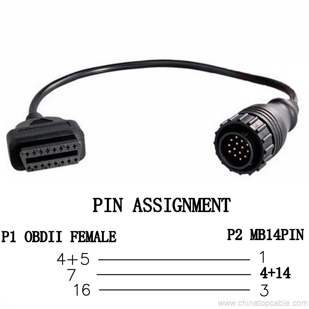
Nissian 14 PIN-kood – 16PIN-kood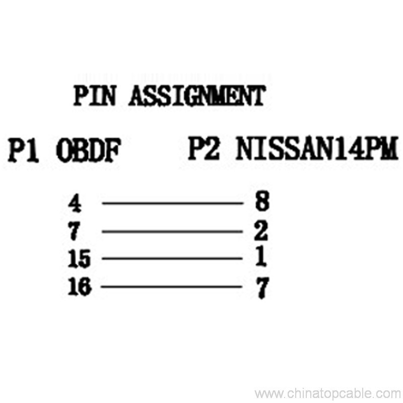
GM12 PIN-16PIN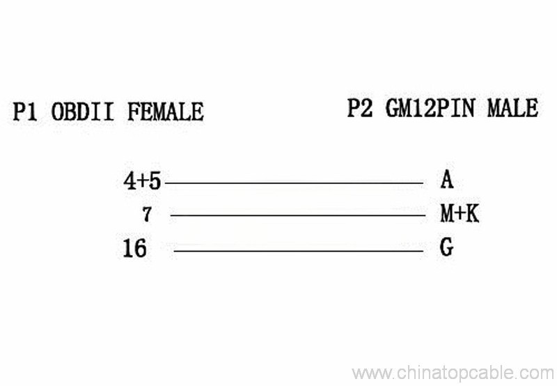
DB9-16 PIN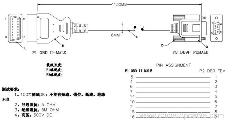
iveco 38pin -16 PIN-kood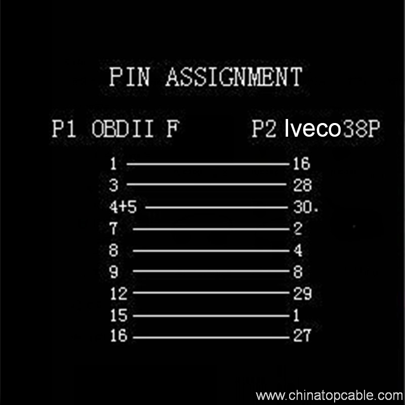
Fiat 3 PIN-kood – 16 PIN-kood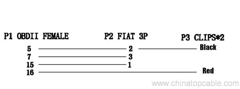
Toyato 22pin – 16 PIN-kood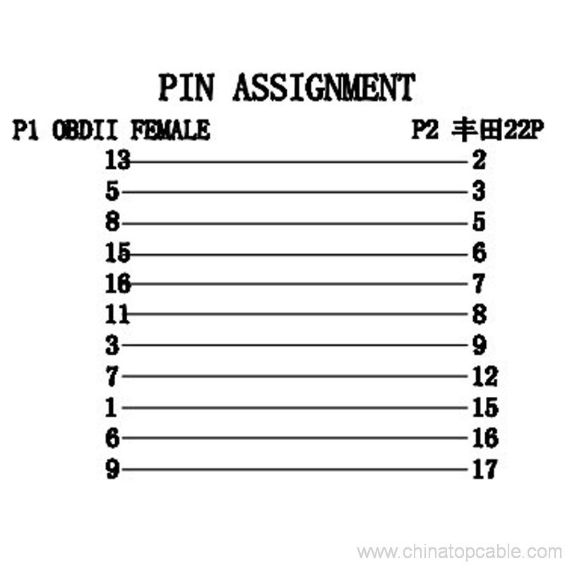
KIA 20 PIN-kood – 16 PIN-kood
Audi 2×2 – 16 PIN-kood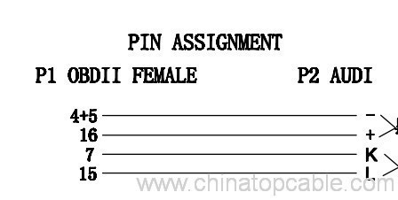
Benz 38 PIN-kood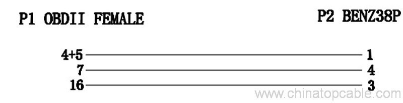
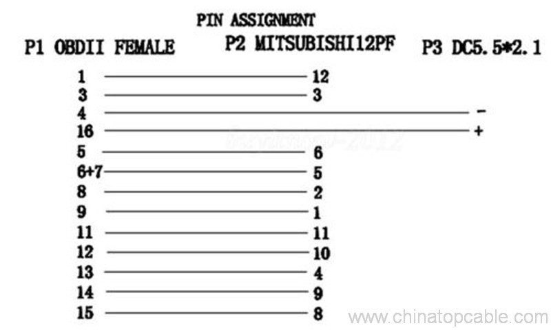
Mitsubishi 12 PIN-kood – 16PIN-kood
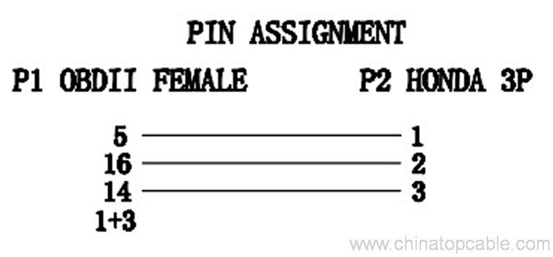
Honda 3pin – 16PIN-kood
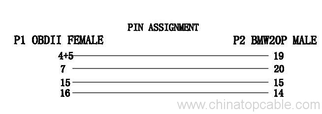
BMW 20 PIN-KOOD – 3 PIN-kood
Subaru 9 PIN-kood – 16 PIN-kood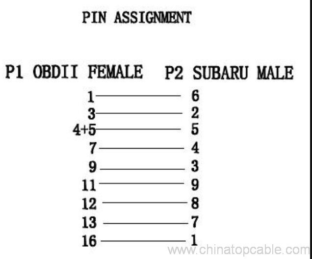
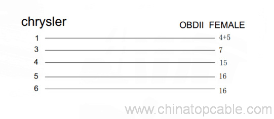
Chrysler 6 PIN-kood