Para OBD2 Final aberto & estender a asignación de pines do cable ,faga clic aquí
Pinout estándar OBD2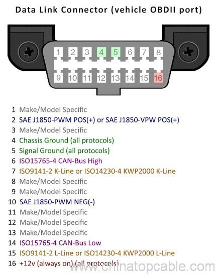
Soure:wiki
Modos
Hainos 10 modos de operación descritos no último estándar OBD-II SAE J1979. Son os seguintes:
| Modo (hex) | descrición |
|---|---|
| 01 | Mostrar datos actuais |
| 02 | Mostrar datos de fotogramas conxelados |
| 03 | Mostra os códigos de problemas de diagnóstico almacenados |
| 04 | Borrar códigos de diagnóstico de problemas e valores almacenados |
| 05 | Resultados da proba, monitorización do sensor de osíxeno (non só CAN) |
| 06 | Resultados da proba, monitorización doutros compoñentes/sistemas (Resultados da proba, Monitorización do sensor de osíxeno só para CAN) |
| 07 | Mostra os códigos de problemas de diagnóstico pendentes (detectado durante o actual ou o último ciclo de condución) |
| 08 | Control do funcionamento do compoñente/sistema a bordo |
| 09 | Solicita información do vehículo |
| 0A | Permanente Códigos de diagnóstico de problemas (DTC) (DTC borrados) |
Os fabricantes de vehículos non están obrigados a admitir todos os modos. Cada fabricante pode definir modos adicionais anteriormente #9 (p.ex.: modo 22 como define SAE J2190 para Ford/GM, modo 21 para Toyota) para outra información p.e. a tensión da batería de tracción en a vehículo eléctrico híbrido (HEV).[2]
PID estándar
A seguinte táboa mostra os PID estándar OBD-II definidos por SAE J1979. Dáse a resposta esperada para cada PID, xunto con información sobre como traducir a resposta en datos significativos. De novo, non todos os vehículos admitirán todos os PID e pode haber PID personalizados definidos polo fabricante que non estean definidos no estándar OBD-II.
Teña en conta que os modos 1 e 2 son basicamente idénticos, excepto ese modo 1 proporciona información actual, mentres que Mode 2 proporciona unha instantánea dos mesmos datos tomados no punto no que se estableceu o último código de diagnóstico. As excepcións son PID 01, que só está dispoñible no modo 1, e PID 02, que só está dispoñible no modo 2. Se Modo 2 PID 02 devolve cero, entón non hai ningunha instantánea e todos os demais modos 2 datos carecen de sentido.
Cando se usa a notación codificada por bits, cantidades como C4 significa bit 4 do byte de datos C. Cada bit está numerado desde 0 para 7, así 7 é o bit máis significativo e 0 é o bit menos significativo.
| A | B | C | D | ||||||||||||||||||||||||||||
| A7 | A6 | A5 | A4 | A3 | A2 | A1 | A0 | B7 | B6 | B5 | B4 | B3 | B2 | B1 | B0 | C7 | C6 | C5 | C4 | C3 | C2 | C1 | C0 | D7 | D6 | D5 | D4 | D3 | D2 | D1 | D0 |
Modo 01
| PID (hex) |
PID (Dec) |
Bytes de datos devoltos | descrición | Valor mínimo | Valor máximo | Unidades | Fórmula[a] |
|---|---|---|---|---|---|---|---|
| 00 | 0 | 4 | PID admitidos [01 – 20] | Bit codificado [A7..D0] == [PID $01..PID $20] Vexa a continuación | |||
| 01 | 1 | 4 | Monitorizar o estado desde que se eliminaron os DTC. (Inclúe lámpada indicadora de mal funcionamento (MIL) estado e número de DTC.) | Bit codificado. Vexa a continuación | |||
| 02 | 2 | 2 | Conxelar DTC | ||||
| 03 | 3 | 2 | Estado do sistema de combustible | Bit codificado. Vexa a continuación | |||
| 04 | 4 | 1 | Carga calculada do motor | 0 | 100 | % | {\estilo de visualización {\tfrac {100}{255}}A} (ou {\estilo de visualización {\tfrac {A}{2.55}}}) |
| 05 | 5 | 1 | Temperatura do refrixerante do motor | -40 | 215 | °C | {\estilo de exhibición A-40} |
| 06 | 6 | 1 | Corte de combustible a curto prazo—Banco 1 | -100 (Reducir o combustible: Demasiado rico) | 99.2 (Engadir combustible: Demasiado delgado) | % |
{\estilo de visualización {\frac {100}{128}}A-100}
(ou {\estilo de visualización {\tfrac {A}{1.28}}-100} ) |
| 07 | 7 | 1 | Corte de combustible a longo prazo—Banco 1 | ||||
| 08 | 8 | 1 | Corte de combustible a curto prazo—Banco 2 | ||||
| 09 | 9 | 1 | Corte de combustible a longo prazo—Banco 2 | ||||
| 0A | 10 | 1 | Presión de combustible (presión manométrica) | 0 | 765 | kPa | {\estilo de visualización 3A} |
| 0B | 11 | 1 | Presión absoluta do colector de admisión | 0 | 255 | kPa | {\estilo de visualización A} |
| 0C | 12 | 2 | RPM do motor | 0 | 16,383.75 | rpm | {\estilo de visualización {\frac {256A+B}{4}}} |
| 0D | 13 | 1 | Velocidade do vehículo | 0 | 255 | km/h | {\estilo de visualización A} |
| 0E | 14 | 1 | Avance de tempo | -64 | 63.5 | ° antes TDC | {\estilo de visualización {\frac {A}{2}}-64} |
| 0F | 15 | 1 | Temperatura do aire de admisión | -40 | 215 | °C | {\estilo de exhibición A-40} |
| 10 | 16 | 2 | MAF caudal de aire | 0 | 655.35 | gramos/seg | {\estilo de visualización {\frac {256A+B}{100}}} |
| 11 | 17 | 1 | Posición do acelerador | 0 | 100 | % | {\estilo de visualización {\tfrac {100}{255}}A} |
| 12 | 18 | 1 | Estado de aire secundario comandado | Bit codificado. Vexa a continuación | |||
| 13 | 19 | 1 | Sensores de osíxeno presentes (en 2 bancos) | [A0..A3] == Banco 1, Sensores 1-4. [A4..A7] == Banco 2… | |||
| 14 | 20 | 2 | Sensor de osíxeno 1 A: Voltaxe B: Corte de combustible a curto prazo |
0 -100 |
1.275 99.2 |
% de voltios |
{\estilo de visualización {\frac {A}{200}}}
{\estilo de visualización {\frac {100}{128}}B-100}
(se B==$FF, o sensor non se utiliza no cálculo de recorte) |
| 15 | 21 | 2 | Sensor de osíxeno 2 A: Voltaxe B: Corte de combustible a curto prazo |
||||
| 16 | 22 | 2 | Sensor de osíxeno 3 A: Voltaxe B: Corte de combustible a curto prazo |
||||
| 17 | 23 | 2 | Sensor de osíxeno 4 A: Voltaxe B: Corte de combustible a curto prazo |
||||
| 18 | 24 | 2 | Sensor de osíxeno 5 A: Voltaxe B: Corte de combustible a curto prazo |
||||
| 19 | 25 | 2 | Sensor de osíxeno 6 A: Voltaxe B: Corte de combustible a curto prazo |
||||
| 1A | 26 | 2 | Sensor de osíxeno 7 A: Voltaxe B: Corte de combustible a curto prazo |
||||
| 1B | 27 | 2 | Sensor de osíxeno 8 A: Voltaxe B: Corte de combustible a curto prazo |
||||
| 1C | 28 | 1 | Estándares OBD aos que cumpre este vehículo | Bit codificado. Vexa a continuación | |||
| 1D | 29 | 1 | Sensores de osíxeno presentes (en 4 bancos) | Similar ao PID 13, pero [A0..A7] == [B1S1, B1S2, B2S1, B2S2, B3S1, B3S2, B4S1, B4S2] | |||
| 1E | 30 | 1 | Estado da entrada auxiliar | A0 == Toma de forza (PTO) estado (1 == activo) [A1..A7] non usado |
|||
| 1F | 31 | 2 | Tempo de execución desde o inicio do motor | 0 | 65,535 | segundos | {\estilo de visualización 256A+B} |
| 20 | 32 | 4 | PID admitidos [21 – 40] | Bit codificado [A7..D0] == [PID $21..PID $40] Vexa a continuación | |||
| 21 | 33 | 2 | Distancia percorrida con lámpada indicadora de avaría (MIL) on | 0 | 65,535 | km | {\estilo de visualización 256A+B} |
| 22 | 34 | 2 | Carril de combustible Presión (en relación ao baleiro do colector) | 0 | 5177.265 | kPa | {\estilo de visualización 0.079(256A+B)} |
| 23 | 35 | 2 | Carril de combustible Presión manométrica (diésel, ou inxección directa de gasolina) | 0 | 655,350 | kPa | {\estilo de visualización 10(256A+B)} |
| 24 | 36 | 4 | Sensor de osíxeno 1 AB: Relación de equivalencia combustible-aire CD: Voltaxe |
0 0 |
< 2 < 8 |
proporción V |
{\estilo de visualización {\frac {2}{65536}}(256A+B)}
{\estilo de visualización {\frac {8}{65536}}(256C+D)}
|
| 25 | 37 | 4 | Sensor de osíxeno 2 AB: Relación de equivalencia combustible-aire CD: Voltaxe |
||||
| 26 | 38 | 4 | Sensor de osíxeno 3 AB: Relación de equivalencia combustible-aire CD: Voltaxe |
||||
| 27 | 39 | 4 | Sensor de osíxeno 4 AB: Relación de equivalencia combustible-aire CD: Voltaxe |
||||
| 28 | 40 | 4 | Sensor de osíxeno 5 AB: Relación de equivalencia combustible-aire CD: Voltaxe |
||||
| 29 | 41 | 4 | Sensor de osíxeno 6 AB: Relación de equivalencia combustible-aire CD: Voltaxe |
||||
| 2A | 42 | 4 | Sensor de osíxeno 7 AB: Relación de equivalencia combustible-aire CD: Voltaxe |
||||
| 2B | 43 | 4 | Sensor de osíxeno 8 AB: Relación de equivalencia combustible-aire CD: Voltaxe |
||||
| 2C | 44 | 1 | Mandado EGR | 0 | 100 | % | {\estilo de visualización {\tfrac {100}{255}}A} |
| 2D | 45 | 1 | Erro EGR | -100 | 99.2 | % | {\estilo de visualización {\tfrac {100}{128}}A-100} |
| 2E | 46 | 1 | Purga evaporativa comandada | 0 | 100 | % | {\estilo de visualización {\tfrac {100}{255}}A} |
| 2F | 47 | 1 | Entrada de nivel do tanque de combustible | 0 | 100 | % | {\estilo de visualización {\tfrac {100}{255}}A} |
| 30 | 48 | 1 | Quecementos desde que se borraron os códigos | 0 | 255 | contar | {\estilo de visualización A} |
| 31 | 49 | 2 | Distancia percorrida desde que se borraron os códigos | 0 | 65,535 | km | {\estilo de visualización 256A+B} |
| 32 | 50 | 2 | Evap. Presión de vapor do sistema | -8,192 | 8191.75 | Pa | {\estilo de visualización {\frac {256A+B}{4}}}(AB é complemento de dous asinado)[3] |
| 33 | 51 | 1 | Presión barométrica absoluta | 0 | 255 | kPa | {\estilo de visualización A} |
| 34 | 52 | 4 | Sensor de osíxeno 1 AB: Relación de equivalencia combustible-aire CD: Actual |
0 -128 |
< 2 <128 |
proporción mA |
{\estilo de visualización {\frac {2}{65536}}(256A+B)}
{\estilo de visualización {\frac {256C+D}{256}}-128}
ou {\estilo de visualización C+{\frac {D}{256}}-128} |
| 35 | 53 | 4 | Sensor de osíxeno 2 AB: Relación de equivalencia combustible-aire CD: Actual |
||||
| 36 | 54 | 4 | Sensor de osíxeno 3 AB: Relación de equivalencia combustible-aire CD: Actual |
||||
| 37 | 55 | 4 | Sensor de osíxeno 4 AB: Relación de equivalencia combustible-aire CD: Actual |
||||
| 38 | 56 | 4 | Sensor de osíxeno 5 AB: Relación de equivalencia combustible-aire CD: Actual |
||||
| 39 | 57 | 4 | Sensor de osíxeno 6 AB: Relación de equivalencia combustible-aire CD: Actual |
||||
| 3A | 58 | 4 | Sensor de osíxeno 7 AB: Relación de equivalencia combustible-aire CD: Actual |
||||
| 3B | 59 | 4 | Sensor de osíxeno 8 AB: Relación de equivalencia combustible-aire CD: Actual |
||||
| 3C | 60 | 2 | Temperatura do catalizador: Banco 1, Sensor 1 | -40 | 6,513.5 | °C | {\estilo de visualización {\frac {256A+B}{10}}-40} |
| 3D | 61 | 2 | Temperatura do catalizador: Banco 2, Sensor 1 | ||||
| 3E | 62 | 2 | Temperatura do catalizador: Banco 1, Sensor 2 | ||||
| 3F | 63 | 2 | Temperatura do catalizador: Banco 2, Sensor 2 | ||||
| 40 | 64 | 4 | PID admitidos [41 – 60] | Bit codificado [A7..D0] == [PID $41..PID $60] Vexa a continuación | |||
| 41 | 65 | 4 | Monitoriza o estado deste ciclo de condución | Bit codificado. Vexa a continuación | |||
| 42 | 66 | 2 | Tensión do módulo de control | 0 | 65.535 | V | {\estilo de visualización {\frac {256A+B}{1000}}} |
| 43 | 67 | 2 | Valor de carga absoluto | 0 | 25,700 | % | {\estilo de visualización {\tfrac {100}{255}}(256A+B)} |
| 44 | 68 | 2 | Relación de equivalencia comandada combustible-aire | 0 | < 2 | proporción | {\estilo de visualización {\tfrac {2}{65536}}(256A+B)} |
| 45 | 69 | 1 | Posición relativa do acelerador | 0 | 100 | % | {\estilo de visualización {\tfrac {100}{255}}A} |
| 46 | 70 | 1 | Temperatura do aire ambiente | -40 | 215 | °C | {\estilo de exhibición A-40} |
| 47 | 71 | 1 | Posición absoluta del acelerador B | 0 | 100 | % | {\estilo de visualización {\frac {100}{255}}A} |
| 48 | 72 | 1 | Posición absoluta do acelerador C | ||||
| 49 | 73 | 1 | Posición del pedal del acelerador D | ||||
| 4A | 74 | 1 | Posición del pedal del acelerador E | ||||
| 4B | 75 | 1 | Pedal acelerador posición F | ||||
| 4C | 76 | 1 | Actuador de acelerador comandado | ||||
| 4D | 77 | 2 | Tempo de execución con MIL activado | 0 | 65,535 | minutos | {\estilo de visualización 256A+B} |
| 4E | 78 | 2 | Tempo transcorrido desde que se solucionaron os códigos de problema | ||||
| 4F | 79 | 4 | Valor máximo da relación de equivalencia combustible-aire, voltaxe do sensor de osíxeno, corrente do sensor de osíxeno, e presión absoluta do colector de admisión | 0, 0, 0, 0 | 255, 255, 255, 2550 | proporción, V, mA, kPa | A, B, C, D*10 |
| 50 | 80 | 4 | Valor máximo para o caudal de aire do sensor de fluxo de aire de masa | 0 | 2550 | g/s | A*10, B, C, e D están reservados para uso futuro |
| 51 | 81 | 1 | Tipo de combustible | Da táboa de tipos de combustible ver a continuación | |||
| 52 | 82 | 1 | Combustible etanol % | 0 | 100 | % | {\estilo de visualización {\tfrac {100}{255}}A} |
| 53 | 83 | 2 | Presión de vapor do sistema de evaporación absoluta | 0 | 327.675 | kPa | {\estilo de visualización {\frac {256A+B}{200}}} |
| 54 | 84 | 2 | Presión de vapor do sistema de evaporación | -32,767 | 32,768 | Pa | ((A*256)+B)-32767 |
| 55 | 85 | 2 | Ajuste de sensor de osíxeno secundario a curto prazo, A: banco 1, B: banco 3 | -100 | 99.2 | % | {\estilo de visualización {\frac {100}{128}}A-100}{\estilo de visualización {\frac {100}{128}}B-100} |
| 56 | 86 | 2 | Ajuste de sensor de osíxeno secundario a longo prazo, A: banco 1, B: banco 3 | ||||
| 57 | 87 | 2 | Ajuste de sensor de osíxeno secundario a curto prazo, A: banco 2, B: banco 4 | ||||
| 58 | 88 | 2 | Ajuste de sensor de osíxeno secundario a longo prazo, A: banco 2, B: banco 4 | ||||
| 59 | 89 | 2 | Carril de combustible presión absoluta | 0 | 655,350 | kPa | {\estilo de visualización 10(256A+B)} |
| 5A | 90 | 1 | Posición relativa do pedal do acelerador | 0 | 100 | % | {\estilo de visualización {\tfrac {100}{255}}A} |
| 5B | 91 | 1 | Duración restante da batería híbrida | 0 | 100 | % | {\estilo de visualización {\tfrac {100}{255}}A} |
| 5C | 92 | 1 | Temperatura do aceite do motor | -40 | 210 | °C | {\estilo de exhibición A-40} |
| 5D | 93 | 2 | Temporización da inxección de combustible | -210.00 | 301.992 | ° | {\estilo de visualización {\frac {256A+B}{128}}-210} |
| 5E | 94 | 2 | Taxa de combustible do motor | 0 | 3276.75 | L/h | {\estilo de visualización {\frac {256A+B}{20}}} |
| 5F | 95 | 1 | Requisitos de emisións aos que está deseñado o vehículo | Bit codificado | |||
| 60 | 96 | 4 | PID admitidos [61 – 80] | Bit codificado [A7..D0] == [PID $61..PID $80] Vexa a continuación | |||
| 61 | 97 | 1 | Motor de demanda do condutor – torque por cento | -125 | 125 | % | A-125 |
| 62 | 98 | 1 | Motor real – torque por cento | -125 | 125 | % | A-125 |
| 63 | 99 | 2 | Par motor de referencia | 0 | 65,535 | Nm | {\estilo de visualización 256A+B} |
| 64 | 100 | 5 | Datos de par porcentual do motor | -125 | 125 | % | A-125 Inactivo B-125 Punto motor 1 C-125 Punto motor 2 D-125 Punto motor 3 E-125 Punto motor 4 |
| 65 | 101 | 2 | Entrada auxiliar / saída compatible | Bit codificado | |||
| 66 | 102 | 5 | Sensor de masa de aire | ||||
| 67 | 103 | 3 | Temperatura do refrixerante do motor | ||||
| 68 | 104 | 7 | Sensor de temperatura de aire de admisión | ||||
| 69 | 105 | 7 | EGR comandado e erro de EGR | ||||
| 6A | 106 | 5 | Control de fluxo de aire de admisión diésel comandado e posición relativa do fluxo de aire de admisión | ||||
| 6B | 107 | 5 | Temperatura de recirculación dos gases de escape | ||||
| 6C | 108 | 5 | Control comandado do actuador do acelerador e posición relativa do acelerador | ||||
| 6D | 109 | 6 | Sistema de control de presión de combustible | ||||
| 6E | 110 | 5 | Sistema de control de presión de inxección | ||||
| 6F | 111 | 3 | Presión de entrada do compresor do turbocompresor | ||||
| 70 | 112 | 9 | Control de presión de aumento | ||||
| 71 | 113 | 5 | Turbo de xeometría variable (VGT) control | ||||
| 72 | 114 | 5 | Control de wastegate | ||||
| 73 | 115 | 5 | Presión de escape | ||||
| 74 | 116 | 5 | Turbocompresor RPM | ||||
| 75 | 117 | 7 | Temperatura do turbocompresor | ||||
| 76 | 118 | 7 | Temperatura do turbocompresor | ||||
| 77 | 119 | 5 | Temperatura do enfriador do aire de carga (CACT) | ||||
| 78 | 120 | 9 | Temperatura dos gases de escape (EGT) Banco 1 | PID especial. Vexa a continuación | |||
| 79 | 121 | 9 | Temperatura dos gases de escape (EGT) Banco 2 | PID especial. Vexa a continuación | |||
| 7A | 122 | 7 | Filtro de partículas diésel (DPF) | ||||
| 7B | 123 | 7 | Filtro de partículas diésel (DPF) | ||||
| 7C | 124 | 9 | Filtro de partículas diésel (DPF) temperatura | ||||
| 7D | 125 | 1 | NOx NTE (Non Exceder) estado da área de control | ||||
| 7E | 126 | 1 | PM NTE (Non Exceder) estado da área de control | ||||
| 7F | 127 | 13 | Tempo de funcionamento do motor | ||||
| 80 | 128 | 4 | PID admitidos [81 – A0] | Bit codificado [A7..D0] == [PID $81..PID $A0] Vexa a continuación | |||
| 81 | 129 | 21 | Tempo de funcionamento do motor para o dispositivo auxiliar de control de emisións(AECD) | ||||
| 82 | 130 | 21 | Tempo de funcionamento do motor para o dispositivo auxiliar de control de emisións(AECD) | ||||
| 83 | 131 | 5 | Sensor NOx | ||||
| 84 | 132 | Temperatura superficial do colector | |||||
| 85 | 133 | Sistema reactivo NOx | |||||
| 86 | 134 | Materias particuladas (PM) sensor | |||||
| 87 | 135 | Presión absoluta do colector de admisión | |||||
| A0 | 160 | 4 | PID admitidos [A1 – C0] | Bit codificado [A7..D0] == [PID $A1..PID $C0] Vexa a continuación | |||
| C0 | 192 | 4 | PID admitidos [C1 – E0] | Bit codificado [A7..D0] == [PID $C1..PID $E0] Vexa a continuación | |||
| C3 | 195 | ? | ? | ? | ? | ? | Devolve numerosos datos, incluíndo ID de condición de condución e velocidade do motor* |
| C4 | 196 | ? | ? | ? | ? | ? | B5 é a solicitude de inactividade do motor B6 é a solicitude de parada do motor* |
| PID (hex) |
PID (Dec) |
Bytes de datos devoltos | descrición | Valor mínimo | Valor máximo | Unidades | Fórmula[a] |


Modo 02[editar]
Modo 02 acepta os mesmos PID que o modo 01, co mesmo significado, pero a información que se dá é de cando se creou o marco conxelado.
Ten que enviar o número de fotograma na sección de datos da mensaxe.
| PID (hex) |
Bytes de datos devoltos | descrición | Valor mínimo | Valor máximo | Unidades | Fórmula[a] |
|---|---|---|---|---|---|---|
| 02 | 2 | DTC que provocou que se almacenase a imaxe conxelada. | BCD codificado. Decodificado como no modo 3 |
Modo 03
| PID (hex) |
Bytes de datos devoltos | descrición | Valor mínimo | Valor máximo | Unidades | Fórmula[a] |
|---|---|---|---|---|---|---|
| N/A | n*6 | Solicita códigos de problema | 3 códigos por marco de mensaxe. Vexa a continuación |
Modo 04[editar]
| PID (hex) |
Bytes de datos devoltos | descrición | Valor mínimo | Valor máximo | Unidades | Fórmula[a] |
|---|---|---|---|---|---|---|
| N/A | 0 | Borrar códigos de problemas / Lámpada indicadora de avaría (MIL) / Comprobe a luz do motor | Borra todos os códigos de problemas almacenados e desactiva o MIL. |
Modo 05
| PID (hex) |
Bytes de datos devoltos | descrición | Valor mínimo | Valor máximo | Unidades | Fórmula[a] |
|---|---|---|---|---|---|---|
| 0100 | ID de monitor OBD compatible ($01 – $20) | |||||
| 0101 | Banco de monitores de sensores de O2 1 Sensor 1 | 0.00 | 1.275 | voltios | 0.005 Voltaje limiar do sensor rico a pobre | |
| 0102 | Banco de monitores de sensores de O2 1 Sensor 2 | 0.00 | 1.275 | voltios | 0.005 Voltaje limiar do sensor rico a pobre | |
| 0103 | Banco de monitores de sensores de O2 1 Sensor 3 | 0.00 | 1.275 | voltios | 0.005 Voltaje limiar do sensor rico a pobre | |
| 0104 | Banco de monitores de sensores de O2 1 Sensor 4 | 0.00 | 1.275 | voltios | 0.005 Voltaje limiar do sensor rico a pobre | |
| 0105 | Banco de monitores de sensores de O2 2 Sensor 1 | 0.00 | 1.275 | voltios | 0.005 Voltaje limiar do sensor rico a pobre | |
| 0106 | Banco de monitores de sensores de O2 2 Sensor 2 | 0.00 | 1.275 | voltios | 0.005 Voltaje limiar do sensor rico a pobre | |
| 0107 | Banco de monitores de sensores de O2 2 Sensor 3 | 0.00 | 1.275 | voltios | 0.005 Voltaje limiar do sensor rico a pobre | |
| 0108 | Banco de monitores de sensores de O2 2 Sensor 4 | 0.00 | 1.275 | voltios | 0.005 Voltaje limiar do sensor rico a pobre | |
| 0109 | Banco de monitores de sensores de O2 3 Sensor 1 | 0.00 | 1.275 | voltios | 0.005 Voltaje limiar do sensor rico a pobre | |
| 010A | Banco de monitores de sensores de O2 3 Sensor 2 | 0.00 | 1.275 | voltios | 0.005 Voltaje limiar do sensor rico a pobre | |
| 010B | Banco de monitores de sensores de O2 3 Sensor 3 | 0.00 | 1.275 | voltios | 0.005 Voltaje limiar do sensor rico a pobre | |
| 010C | Banco de monitores de sensores de O2 3 Sensor 4 | 0.00 | 1.275 | voltios | 0.005 Voltaje limiar do sensor rico a pobre | |
| 010D | Banco de monitores de sensores de O2 4 Sensor 1 | 0.00 | 1.275 | voltios | 0.005 Voltaje limiar do sensor rico a pobre | |
| 010E | Banco de monitores de sensores de O2 4 Sensor 2 | 0.00 | 1.275 | voltios | 0.005 Voltaje limiar do sensor rico a pobre | |
| 010F | Banco de monitores de sensores de O2 4 Sensor 3 | 0.00 | 1.275 | voltios | 0.005 Voltaje limiar do sensor rico a pobre | |
| 0110 | Banco de monitores de sensores de O2 4 Sensor 4 | 0.00 | 1.275 | voltios | 0.005 Voltaje limiar do sensor rico a pobre | |
| 0201 | Banco de monitores de sensores de O2 1 Sensor 1 | 0.00 | 1.275 | voltios | 0.005 Tensión de umbral do sensor Lean to Rich | |
| 0202 | Banco de monitores de sensores de O2 1 Sensor 2 | 0.00 | 1.275 | voltios | 0.005 Tensión de umbral do sensor Lean to Rich | |
| 0203 | Banco de monitores de sensores de O2 1 Sensor 3 | 0.00 | 1.275 | voltios | 0.005 Tensión de umbral do sensor Lean to Rich | |
| 0204 | Banco de monitores de sensores de O2 1 Sensor 4 | 0.00 | 1.275 | voltios | 0.005 Tensión de umbral do sensor Lean to Rich | |
| 0205 | Banco de monitores de sensores de O2 2 Sensor 1 | 0.00 | 1.275 | voltios | 0.005 Tensión de umbral do sensor Lean to Rich | |
| 0206 | Banco de monitores de sensores de O2 2 Sensor 2 | 0.00 | 1.275 | voltios | 0.005 Tensión de umbral do sensor Lean to Rich | |
| 0207 | Banco de monitores de sensores de O2 2 Sensor 3 | 0.00 | 1.275 | voltios | 0.005 Tensión de umbral do sensor Lean to Rich | |
| 0208 | Banco de monitores de sensores de O2 2 Sensor 4 | 0.00 | 1.275 | voltios | 0.005 Tensión de umbral do sensor Lean to Rich | |
| 0209 | Banco de monitores de sensores de O2 3 Sensor 1 | 0.00 | 1.275 | voltios | 0.005 Tensión de umbral do sensor Lean to Rich | |
| 020A | Banco de monitores de sensores de O2 3 Sensor 2 | 0.00 | 1.275 | voltios | 0.005 Tensión de umbral do sensor Lean to Rich | |
| 020B | Banco de monitores de sensores de O2 3 Sensor 3 | 0.00 | 1.275 | voltios | 0.005 Tensión de umbral do sensor Lean to Rich | |
| 020C | Banco de monitores de sensores de O2 3 Sensor 4 | 0.00 | 1.275 | voltios | 0.005 Tensión de umbral do sensor Lean to Rich | |
| 020D | Banco de monitores de sensores de O2 4 Sensor 1 | 0.00 | 1.275 | voltios | 0.005 Tensión de umbral do sensor Lean to Rich | |
| 020E | Banco de monitores de sensores de O2 4 Sensor 2 | 0.00 | 1.275 | voltios | 0.005 Tensión de umbral do sensor Lean to Rich | |
| 020F | Banco de monitores de sensores de O2 4 Sensor 3 | 0.00 | 1.275 | voltios | 0.005 Tensión de umbral do sensor Lean to Rich | |
| 0210 | Banco de monitores de sensores de O2 4 Sensor 4 | 0.00 | 1.275 | voltios | 0.005 Tensión de umbral do sensor Lean to Rich | |
| PID (hex) |
Bytes de datos devoltos | descrición | Valor mínimo | Valor máximo | Unidades | Fórmula[a] |
Modo 09
| PID (hex) |
Bytes de datos devoltos | descrición | Valor mínimo | Valor máximo | Unidades | Fórmula[a] |
|---|---|---|---|---|---|---|
| 00 | 4 | Modo 9 PID soportados (01 para 20) | Bit codificado. [A7..D0] = [PID $01..PID $20] Vexa a continuación | |||
| 01 | 1 | Número de mensaxes VIN no PID 02. Só para ISO 9141-2, ISO 14230-4 e SAE J1850. | Normalmente o valor será 5. | |||
| 02 | 17 | Número de identificación do vehículo (VIN) | 17-char VIÑO, Codificación ASCII e recheo á esquerda con caracteres nulos (0x00) se é necesario. | |||
| 03 | 1 | Conta de mensaxes de ID de calibración para PID 04. Só para ISO 9141-2, ISO 14230-4 e SAE J1850. | Será un múltiplo de 4 (4 necesítanse mensaxes para cada ID). | |||
| 04 | 16,32,48,64.. | ID de calibración | Ata 16 Caracteres ASCII. Os bytes de datos non utilizados indicaranse como bytes nulos (0x00). Pódense emitir varios CALID (16 bytes cada un) | |||
| 05 | 1 | Números de verificación de calibración (CVN) número de mensaxes para o PID 06. Só para ISO 9141-2, ISO 14230-4 e SAE J1850. | ||||
| 06 | 4,8,12,16 | Números de verificación de calibración (CVN) Pódense emitir varios CVN (4 bytes cada un) o número de CVN e CALID debe coincidir | Datos en bruto recheados á esquerda con caracteres nulos (0x00). Normalmente móstrase como cadea hexadecimal. | |||
| 07 | 1 | Reconto de mensaxes de seguimento de rendemento en uso para o PID 08 e 0B. Só para ISO 9141-2, ISO 14230-4 e SAE J1850. | 8 | 10 | 8 se dezaseis anos (16) os valores deben ser comunicados, 9 se dezaoito (18) os valores deben ser comunicados, e 10 se vinte (20) os valores deben ser comunicados (unha mensaxe informa de dous valores, cada un consta de dous bytes). | |
| 08 | 4 | Seguimento do rendemento en uso para vehículos de ignición por chispa | 4 ou 5 mensaxes, contén cada un 4 bytes (dous valores). Vexa a continuación | |||
| 09 | 1 | Conta de mensaxes de nome da ECU para o PID 0A | ||||
| 0A | 20 | Nome da ECU | Codificado en ASCII. Recheo á dereita con caracteres nulos (0x00). | |||
| 0B | 4 | Seguimento do rendemento en uso para vehículos de ignición por compresión | 5 mensaxes, contén cada un 4 bytes (dous valores). Vexa a continuación | |||
| PID (hex) |
Bytes de datos devoltos | descrición | Valor mínimo | Valor máximo | Unidades | Fórmula[a] |
PID codificados bit a bit
Algúns dos PID da táboa anterior non se poden explicar cunha fórmula sinxela. Aquí se ofrece unha explicación máis elaborada destes datos:
Modo 1 PID 00
Devolve unha solicitude para este PID 4 bytes de datos. Cada bit, dende MSB para LSB, representa un dos seguintes 32 PID e está dando información sobre se é compatible.
Por exemplo, se a resposta do coche é BE1FA813, pódese decodificar así:
| Hexadecimal | B | E | 1 | F | A | 8 | 1 | 3 | ||||||||||||||||||||||||
|---|---|---|---|---|---|---|---|---|---|---|---|---|---|---|---|---|---|---|---|---|---|---|---|---|---|---|---|---|---|---|---|---|
| Binario | 1 | 0 | 1 | 1 | 1 | 1 | 1 | 0 | 0 | 0 | 0 | 1 | 1 | 1 | 1 | 1 | 1 | 0 | 1 | 0 | 1 | 0 | 0 | 0 | 0 | 0 | 0 | 1 | 0 | 0 | 1 | 1 |
| Soportado? | Si | Non | Si | Si | Si | Si | Si | Non | Non | Non | Non | Si | Si | Si | Si | Si | Si | Non | Si | Non | Si | Non | Non | Non | Non | Non | Non | Si | Non | Non | Si | Si |
| Número PID | 01 | 02 | 03 | 04 | 05 | 06 | 07 | 08 | 09 | 0A | 0B | 0C | 0D | 0E | 0F | 10 | 11 | 12 | 13 | 14 | 15 | 16 | 17 | 18 | 19 | 1A | 1B | 1C | 1D | 1E | 1F | 20 |
Entón, os PID admitidos son: 01, 03, 04, 05, 06, 07, 0C, 0D, 0E, 0F, 10, 11, 13, 15, 1C, 1F e 20
Modo 1 PID 01
Devolve unha solicitude para este PID 4 bytes de datos, etiquetados A B C e D.
O primeiro byte(A) contén dúas informacións. Bit A7 (MSB do byte A, o primeiro byte) indica se o MIL ou non (comprobar a luz do motor) está iluminado. Bits A6 a través de A0representan o número de códigos de problemas de diagnóstico marcados actualmente na ECU.
O segundo, terceiro, e cuartos bytes(B, C e D) proporcionar información sobre a dispoñibilidade e integridade de determinadas probas a bordo. Teña en conta esa proba dispoñibilidade está indicado por conxunto (1) pouco e integridade indícase mediante reset (0) pouco.
| Bit | nome | Definición |
|---|---|---|
| A7 | MIL | Desactivado ou Activado, indica se o CEL/MIL está activado (ou debería estar activado) |
| A6–A0 | DTC_CNT | Número de DTC confirmados relacionados coas emisións dispoñibles para mostrar. |
| B7 | RESERVADOS | Reservado (debería ser 0) |
| B3 | SEN NOME | 0 = Monitores de ignición por chispa admitidos (p.ex. Motores Otto ou Wankel) 1 = Monitores de ignición por compresión compatibles (p.ex. Motores diésel) |
Aquí están as definicións comúns do bit B, están baseados en probas.
| Proba dispoñible | Proba incompleta | |
|---|---|---|
| Compoñentes | B2 | B6 |
| Sistema de combustible | B1 | B5 |
| Fallo de lume | B0 | B4 |
O terceiro e cuarto bytes deben interpretarse de forma diferente dependendo de se o motor é faísca ignición (p.ex. Motores Otto ou Wankel) ou ignición por compresión (p.ex. Motores diésel). No segundo (B) byte, pouco 3 indica como interpretar os bytes C e D, con 0 sendo chispa (Otto ou Wankel) e 1 (conxunto) sendo compresión (Diesel).
Os bytes C e D para monitores de ignición por chispa (p.ex. Motores Otto ou Wankel):
| Proba dispoñible | Proba incompleta | |
|---|---|---|
| Sistema EGR | C7 | D7 |
| Calentador de sensor de osíxeno | C6 | D6 |
| Sensor de osíxeno | C5 | D5 |
| Refrigerante A/C | C4 | D4 |
| Sistema de aire secundario | C3 | D3 |
| Sistema evaporativo | C2 | D2 |
| Catalizador quentado | C1 | D1 |
| Catalizador | C0 | D0 |
E os bytes C e D para monitores de ignición por compresión (Motores diésel):
| Proba dispoñible | Proba incompleta | |
|---|---|---|
| Sistema EGR e/ou VVT | C7 | D7 |
| Monitorización do filtro PM | C6 | D6 |
| Sensor de gases de escape | C5 | D5 |
| – Reservado – | C4 | D4 |
| Presión de aumento | C3 | D3 |
| – Reservado – | C2 | D2 |
| Monitor de NOx/SCR | C1 | D1 |
| Catalizador NMHC[a] | C0 | D0 |
- Salta cara arriba^ NMHC maio significa hidrocarburos non metanos, pero J1979 non nos ilumina. A tradución sería o sensor de amoníaco no catalizador SCR.
Modo 1 PID 41
Devolve unha solicitude para este PID 4 bytes de datos. O primeiro byte é sempre cero. O segundo, terceiro, e os cuartos bytes dan información sobre a dispoñibilidade e integridade de certas probas a bordo. Como co PID 01, o terceiro e cuarto bytes deben interpretarse de forma diferente dependendo do tipo de ignición (B3) – con 0 sendo chispa e 1 (conxunto) sendo compresión. Teña en conta de novo esa proba dispoñibilidade está representado por un conxunto (1) pouco e integridade está representado por un reset (0) pouco.
Aquí están as definicións comúns do bit B, están baseados en probas.
| Proba dispoñible | Proba incompleta | |
|---|---|---|
| Compoñentes | B2 | B6 |
| Sistema de combustible | B1 | B5 |
| Fallo de lume | B0 | B4 |
Os bytes C e D para monitores de ignición por chispa (p.ex. Motores Otto ou Wankel):
| Proba dispoñible | Proba incompleta | |
|---|---|---|
| Sistema EGR | C7 | D7 |
| Calentador de sensor de osíxeno | C6 | D6 |
| Sensor de osíxeno | C5 | D5 |
| Refrigerante A/C | C4 | D4 |
| Sistema de aire secundario | C3 | D3 |
| Sistema evaporativo | C2 | D2 |
| Catalizador quentado | C1 | D1 |
| Catalizador | C0 | D0 |
E os bytes C e D para monitores de ignición por compresión (Motores diésel):
| Proba dispoñible | Proba incompleta | |
|---|---|---|
| Sistema EGR e/ou VVT | C7 | D7 |
| Monitorización do filtro PM | C6 | D6 |
| Sensor de gases de escape | C5 | D5 |
| – Reservado – | C4 | D4 |
| Presión de aumento | C3 | D3 |
| – Reservado – | C2 | D2 |
| Monitor de NOx/SCR | C1 | D1 |
| Catalizador NMHC[a] | C0 | D0 |
- Salta cara arriba^ NMHC maio significa hidrocarburos non metanos, pero J1979 non nos ilumina. A tradución sería o sensor de amoníaco no catalizador SCR.
Modo 1 PID 78
Devolverase unha solicitude para este PID 9 bytes de datos. O primeiro byte é un campo codificado en bits que indica cal EGT os sensores son compatibles:
| Byte | descrición |
|---|---|
| A | Sensores EGT compatibles |
| B–C | Temperatura lida por EGT11 |
| D–E | Temperatura lida por EGT12 |
| F–G | Temperatura lida por EGT13 |
| H–eu | Temperatura lida por EGT14 |
O primeiro byte está codificado por bits do seguinte xeito:
| Bit | descrición |
|---|---|
| A7–A4 | Reservado |
| A3 | Banco EGT 1, sensor 4 Soportado? |
| A2 | Banco EGT 1, sensor 3 Soportado? |
| A1 | Banco EGT 1, sensor 2 Soportado? |
| A0 | Banco EGT 1, sensor 1 Soportado? |
Os bytes restantes son 16 bits enteiros que indican a temperatura en graos Celsius no intervalo -40 para 6513.5 (escala 0.1), usando o habitual {\estilo de visualización (A veces 256+B)/10-40} fórmula (MSB é A, LSB é B). Só os valores para os que se admite o sensor correspondente son significativos.

A mesma estrutura aplícase ao PID 79, pero os valores son para sensores de banco 2.
Modo 3 (non se precisa PID)
A solicitude deste modo devolve unha lista dos DTC que se estableceron. A lista está encapsulada usando o ISO 15765-2 protocolo.
Se hai dous ou menos DTC (4 bytes) son devoltos nun marco único ISO-TP (SF). Tres ou máis DTC da lista infórmanse en varios fotogramas, co reconto exacto de tramas dependendo do tipo de comunicación e dos detalles do enderezo.
Cada código de problema require 2 bytes para describir. A descrición de texto dun código de problema pódese descodificar do seguinte xeito. O primeiro carácter do código de problema está determinado polos dous primeiros bits do primeiro byte:
| A7–A6 | Primeiro carácter DTC |
|---|---|
| 00 | P – Tren motriz |
| 01 | C – Chasis |
| 10 | B – Corpo |
| 11 | U – Rede |
Os dous díxitos seguintes están codificados como 2 bits. O segundo carácter do DTC é un número definido pola seguinte táboa:
| A5–A4 | Segundo carácter DTC |
|---|---|
| 00 | 0 |
| 01 | 1 |
| 10 | 2 |
| 11 | 3 |
O terceiro carácter do DTC é un número definido por
| A3–A0 | Terceiro carácter DTC |
|---|---|
| 0000 | 0 |
| 0001 | 1 |
| 0010 | 2 |
| 0011 | 3 |
| 0100 | 4 |
| 0101 | 5 |
| 0110 | 6 |
| 0111 | 7 |
| 1000 | 8 |
| 1001 | 9 |
| 1010 | A |
| 1011 | B |
| 1100 | C |
| 1101 | D |
| 1110 | E |
| 1111 | F |
O cuarto e o quinto caracteres defínense do mesmo xeito que o terceiro, pero usando bits B7–B4 e B3–B0. O código de cinco caracteres resultante debería parecer algo así “U0158” e pódese buscar nunha táboa de DTC OBD-II. Caracteres hexadecimais (0-9, A-F), aínda que relativamente rara, están permitidos no último 3 posicións do propio código.
Modo 9 PID 08
Ofrece información sobre o rendemento en uso dos bancos de catalizadores, bancos de sensores de osíxeno, Sistemas de detección de fugas por evaporación, Sistemas EGR e sistema de aire secundario.
O numerador de cada compoñente ou sistema fai un seguimento do número de veces que se atoparon todas as condicións necesarias para que un monitor específico detecte un mal funcionamento. O denominador de cada compoñente ou sistema fai un seguimento do número de veces que o vehículo foi utilizado nas condicións especificadas.
O reconto de elementos de datos debe informarse ao principio (o primeiro byte).
Todos os elementos de datos do rexistro de seguimento de rendemento en uso constan de dous (2) bytes e infórmanse nesta orde (cada mensaxe contén dous elementos, polo tanto, a lonxitude da mensaxe é 4).
| Mnemónico | descrición |
|---|---|
| OBDCOND | Condicións de vixilancia OBD atopadas |
| IGNCNTR | Contador de ignición |
| CATCOMP1 | Catalyst Monitor Completion Counts Bank 1 |
| CATCOND1 | Catalyst Monitor Condicións atopadas Banco de contas 1 |
| CATCOMP2 | Catalyst Monitor Completion Counts Bank 2 |
| CATCOND2 | Catalyst Monitor Condicións atopadas Banco de contas 2 |
| O2SCOMP1 | Banco de contas de finalización do monitor do sensor de O2 1 |
| O2SCOND1 | Sensor de O2 Monitor Condicións atopadas Banco de contas 1 |
| O2SCOMP2 | Banco de contas de finalización do monitor do sensor de O2 2 |
| O2SCOND2 | Sensor de O2 Monitor Condicións atopadas Banco de contas 2 |
| EGRCOMP | Contas de condicións de finalización do monitor EGR |
| EGRCOND | Condicións de monitor EGR atopadas Contas |
| AIRCOMP | Conta de condicións de finalización do monitor AIR (Aire secundario) |
| AIRE ACONDICIONADO | AIR Monitor Condicións atopadas Contas (Aire secundario) |
| EVAPCOMP | Contas de condicións de finalización do monitor EVAP |
| EVAPCOND | EVAP Monitor Condicións atopadas Contas |
| SO2SCOMP1 | Banco de contas de finalización do monitor do sensor de O2 secundario 1 |
| SO2SCOND1 | Sensor de O2 secundario Monitor de condicións atopadas Banco de contas 1 |
| SO2SCOMP2 | Banco de contas de finalización do monitor do sensor de O2 secundario 2 |
| SO2SCOND2 | Sensor de O2 secundario Monitor de condicións atopadas Banco de contas 2 |
Modo 9 PID 0B
Ofrece información sobre o rendemento en uso do catalizador NMHC, Monitor de catalizador de NOx, Monitor de absorción de NOx, Monitor de filtro PM, Monitor de sensor de gases de escape, Monitor EGR/VVT, monitor de presión de sobrealimentación e monitor do sistema de combustible.
Todos os elementos de datos constan de dous (2) bytes e infórmanse nesta orde (cada mensaxe contén dous elementos, polo tanto, a lonxitude da mensaxe é 4):
| Mnemónico | descrición |
|---|---|
| OBDCOND | Condicións de vixilancia OBD atopadas |
| IGNCNTR | Contador de ignición |
| HCCATCOMP | NMHC Catalyst Monitor Completion Condition Counts |
| HCCATCOND | NMHC Catalyst Monitor Condicións atopadas Contas |
| NCATCOMP | Contas de condicións de finalización do monitor de catalizador NOx/SCR |
| NCATCOND | Contas atopadas no monitor de catalizador NOx/SCR |
| NADSCOMP | Contas de condición de finalización do monitor de adsorbedor de NOx |
| NADSCOND | Condicións do monitor de adsorbedores de NOx atopadas |
| PMCOMP | Contas de condicións de finalización do monitor de filtro PM |
| PMCOND | Condicións do monitor de filtro PM atopadas |
| EGCOMP | Conta de condicións de finalización do monitor do sensor de gases de escape |
| EGSCOND | Condicións do monitor do sensor de gases de escape atopadas |
| EGRCOMP | Contas de condicións de realización do monitor EGR e/ou VVT |
| EGRCOND | Contas atopadas nas condicións do monitor EGR e/ou VVT |
| BPCOMP | Contas de condicións de finalización do monitor de presión de sobrealimentación |
| BPCOND | Condicións do monitor de presión de sobrealimentación atopadas |
| COMBUSTIBLE | Contas de condicións de finalización do monitor de combustible |
| CONDICIÓN DE COMBUSTIBLE | Condicións de monitor de combustible atopadas Contas |
PID enumerados[editar]
Algúns PID deben ser interpretados especialmente, e non están necesariamente codificados exactamente bit a bit, ou en calquera escala. Os valores destes PID son enumerados.
Modo 1 PID 03[editar]
Devolve unha solicitude para este PID 2 bytes de datos. O primeiro byte describe o sistema de combustible #1.
| Valor | descrición |
|---|---|
| 1 | Lazo aberto debido a unha temperatura insuficiente do motor |
| 2 | Bucle pechado, utilizando o sensor de osíxeno para determinar a mestura de combustible |
| 4 | Bucle aberto debido á carga do motor OU corte de combustible debido á desaceleración |
| 8 | Bucle aberto debido a un fallo do sistema |
| 16 | Bucle pechado, usando polo menos un sensor de osíxeno pero hai un fallo no sistema de retroalimentación |
Calquera outro valor é unha resposta non válida. Só pode haber un conxunto de bits como máximo.
O segundo byte describe o sistema de combustible #2 (se existe) e está codificado de forma idéntica ao primeiro byte.
Modo 1 PID 12
Unha solicitude para este PID devolve un único byte de datos que describe o estado do aire secundario.
| Valor | descrición |
|---|---|
| 1 | Río arriba |
| 2 | Abaixo do convertidor catalítico |
| 4 | Desde o ambiente exterior ou apagado |
| 8 | Bomba encendida para diagnóstico |
Calquera outro valor é unha resposta non válida. Só pode haber un conxunto de bits como máximo.
Modo 1 PID 1C
Unha solicitude para este PID devolve un único byte de datos que describe cales estándares OBD foi deseñada para cumprir esta ECU. A continuación móstranse os diferentes valores que pode conter o byte de datos, xunto ao que significan:
| Valor | descrición |
|---|---|
| 1 | OBD-II tal e como se define CARB |
| 2 | OBD tal e como o define EPA |
| 3 | OBD e OBD-II |
| 4 | OBD-I |
| 5 | Non é compatible con OBD |
| 6 | EOBD (Europa) |
| 7 | EOBD e OBD-II |
| 8 | EOBD e OBD |
| 9 | EOBD, OBD e OBD II |
| 10 | EMPREGO (Xapón) |
| 11 | JOBD e OBD II |
| 12 | JOBD e EOBD |
| 13 | EMPREGO, EOBD, e OBD II |
| 14 | Reservado |
| 15 | Reservado |
| 16 | Reservado |
| 17 | Diagnóstico do fabricante do motor (EMD) |
| 18 | Diagnóstico do fabricante do motor mellorado (EMD+) |
| 19 | Diagnóstico a bordo de alta resistencia (Infantil/Parcial) (HD OBD-C) |
| 20 | Diagnóstico a bordo de alta resistencia (HD OBD) |
| 21 | OBD harmonizado a nivel mundial (WWH OBD) |
| 22 | Reservado |
| 23 | Heavy Duty Euro OBD Fase I sen control de NOx (HD EOBD-I) |
| 24 | Heavy Duty Euro OBD Fase I con control de NOx (HD EOBD-I N) |
| 25 | Heavy Duty Euro OBD Fase II sen control de NOx (HD EOBD-II) |
| 26 | Heavy Duty Euro OBD Stage II con control de NOx (HD EOBD-II N) |
| 27 | Reservado |
| 28 | Fase OBD Brasil 1 (OBDBr-1) |
| 29 | Fase OBD Brasil 2 (ODBr-2) |
| 30 | OBD coreano (KOBD) |
| 31 | India OBD I (IOBD I) |
| 32 | India OBD II (IOBD II) |
| 33 | Heavy Duty Euro OBD Fase VI (HD EOBD-IV) |
| 34-250 | Reservado |
| 251-255 | Non dispoñible para asignación (SAE J1939 significado especial) |
Codificación do tipo de combustible
Modo 1 PID 51 devolve un valor dunha lista enumerada que indica o tipo de combustible do vehículo. O tipo de combustible devólvese como un único byte, e o valor vén dado pola seguinte táboa:
| Valor | descrición |
|---|---|
| 0 | Non dispoñible |
| 1 | Gasolina |
| 2 | Metanol |
| 3 | Etanol |
| 4 | Diesel |
| 5 | GLP |
| 6 | GNC |
| 7 | Propano |
| 8 | Eléctrico |
| 9 | Bifuel funcionando a gasolina |
| 10 | Bifuel con metanol |
| 11 | Bifuel que funciona con etanol |
| 12 | Bifuel que funciona con GLP |
| 13 | Bifuel que funciona con GNC |
| 14 | Bifuel con propano |
| 15 | Bifuel en funcionamento Electricidade |
| 16 | Motor eléctrico e de combustión bifuel |
| 17 | Gasolina híbrida |
| 18 | Etanol híbrido |
| 19 | Diesel híbrido |
| 20 | Híbrido Eléctrico |
| 21 | Motor híbrido eléctrico e de combustión |
| 22 | Híbrido Rexenerativo |
| 23 | Bifuel con diésel |
Calquera outro valor está reservado por ISO/SAE. Actualmente non hai definicións para vehículo de combustible flexible.
PID non estándar
A maioría de todos os PID OBD-II en uso non son estándar. Para a maioría dos vehículos modernos, Hai moitas máis funcións compatibles coa interface OBD-II que as cubertas polos PID estándar, e hai unha superposición relativamente pequena entre os fabricantes de vehículos para estes PID non estándar.
Hai información moi limitada dispoñible no dominio público para os PID non estándar. A fonte principal de información sobre PID non estándar de diferentes fabricantes é mantida polos Estados Unidos Instituto de Equipos e Ferramentas e só dispoñible para os membros. O prezo da adhesión a ETI para acceder aos códigos de dixitalización varía en función do tamaño da empresa definido polas vendas anuais de ferramentas e equipos automotivos en América do Norte:
| Vendas anuais en América do Norte | Cuotas anuais |
|---|---|
| Baixo $10,000,000 | $5,000 |
| $10,000,000 – $50,000,000 | $7,500 |
| Maior que $50,000,000 | $10,000 |
Porén, mesmo a adhesión a ETI non proporcionará documentación completa para os PID non estándar. Estado ETI:[4][5]
Algúns OEM néganse a usar ETI como fonte única de información sobre ferramentas de dixitalización. Prefiren facer negocios con cada empresa de ferramentas por separado. Estas empresas tamén esixen que celebres un contrato con elas. Os cargos varían, pero aquí tes unha instantánea do 13 de abril, 2015 dos cargos anuais:
GM $50,000 Honda $5,000 Suzuki $1,000 BMW $25,500 máis $2,000 por actualización. As actualizacións ocorren anualmente.
CAN (11-pouco) formato bus
A consulta e resposta PID prodúcese no bus CAN do vehículo. As solicitudes e respostas OBD estándar usan enderezos funcionais. O lector de diagnóstico inicia unha consulta usando CAN ID 7DFh[precisa aclaración], que actúa como enderezo de difusión, e acepta respostas de calquera ID no rango de 7E8h a 7EFh. Os ECU que poden responder a consultas OBD escoitan tanto o ID de emisión funcional de 7DFh como un ID asignado no rango de 7E0h a 7E7h. A súa resposta ten un ID do seu ID máis asignado 8 p.ex. 7E8h ata 7EFh.
Este enfoque permite ata oito ECU, cada un respondendo de forma independente ás consultas OBD. O lector de diagnóstico pode usar o ID no marco de resposta da ECU para continuar a comunicación cunha ECU específica. En particular, a comunicación multi-frame require unha resposta ao ID específico da ECU en lugar do ID 7DFh.
O bus CAN tamén se pode utilizar para a comunicación máis aló das mensaxes OBD estándar. O direccionamento físico usa ID CAN particulares para módulos específicos (p.ex., 720h para o grupo de instrumentos en Fords) con cargas útiles de marco propietarios.
Consulta
A consulta PID funcional envíase ao vehículo no bus CAN no ID 7DFh, usando 8 bytes de datos. Os bytes son:
| Byte | ||||||||
|---|---|---|---|---|---|---|---|---|
| Tipo PID | 0 | 1 | 2 | 3 | 4 | 5 | 6 | 7 |
| Norma SAE | Número de adicional bytes de datos: 2 |
Modo 01 = mostrar os datos actuais; 02 = congelar fotograma; etc. |
Código PID (p.ex.: 05 = Temperatura do refrixerante do motor) |
non usado (pode ser 55h) |
||||
| Específico do vehículo | Número de adicional bytes de datos: 3 |
Modo personalizado: (p.ex.: 22 = datos mellorados) | Código PID (p.ex.: 4980h) |
non usado (pode ser 00h ou 55h) |
||||
Resposta
O vehículo responde á consulta PID no bus CAN con ID de mensaxes que dependen do módulo que respondeu. Normalmente o motor ou a ECU principal responde ao ID 7E8h. Outros módulos, como o controlador híbrido ou o controlador de batería dun Prius, responder ás 07E9h, 07EAh, 07EBh, etc. Estes son 8h máis altos que a dirección física á que responde o módulo. Aínda que o número de bytes no valor devolto é variable, a mensaxe utiliza 8 bytes de datos independentemente (bus CAN formato de protocolo Frameformat con 8 bytes de datos). Os bytes son:
| Byte | ||||||||
|---|---|---|---|---|---|---|---|---|
| Tipo PID | 0 | 1 | 2 | 3 | 4 | 5 | 6 | 7 |
| Norma SAE 7E8h, 7E9h, 7EAh, etc. |
Número de adicional bytes de datos: 3 para 6 |
Modo personalizado Igual que a consulta, excepto que se engaden 40h ao valor do modo. Entón: 41h = mostrar os datos actuais; 42h = congelar fotograma; etc. |
Código PID (p.ex.: 05 = Temperatura do refrixerante do motor) |
valor do parámetro especificado, byte 0 | valor, byte 1 (opcional) | valor, byte 2 (opcional) | valor, byte 3 (opcional) | non usado (pode ser 00h ou 55h) |
| Específico do vehículo 7E8h, ou 8h + ID físico do módulo. |
Número de adicional bytes de datos: 4para 7 |
Modo personalizado: igual que a consulta, excepto que se engaden 40h ao valor do modo.(p.ex.: 62h = resposta á solicitude do modo 22h) | Código PID (p.ex.: 4980h) |
valor do parámetro especificado, byte 0 | valor, byte 1 (opcional) | valor, byte 2 (opcional) | valor, byte 3 (opcional) | |
| Específico do vehículo 7E8h, ou 8h + ID físico do módulo. |
Número de adicional bytes de datos: 3 |
7Esta é unha resposta xeral que normalmente indica que o módulo non recoñece a solicitude. | Modo personalizado: (p.ex.: 22h = datos de diagnóstico mellorados por PID, 21h = datos mellorados por compensación) | 31h | non usado (pode ser ás 00h) |
|||
Benz 14 pines – 16Pino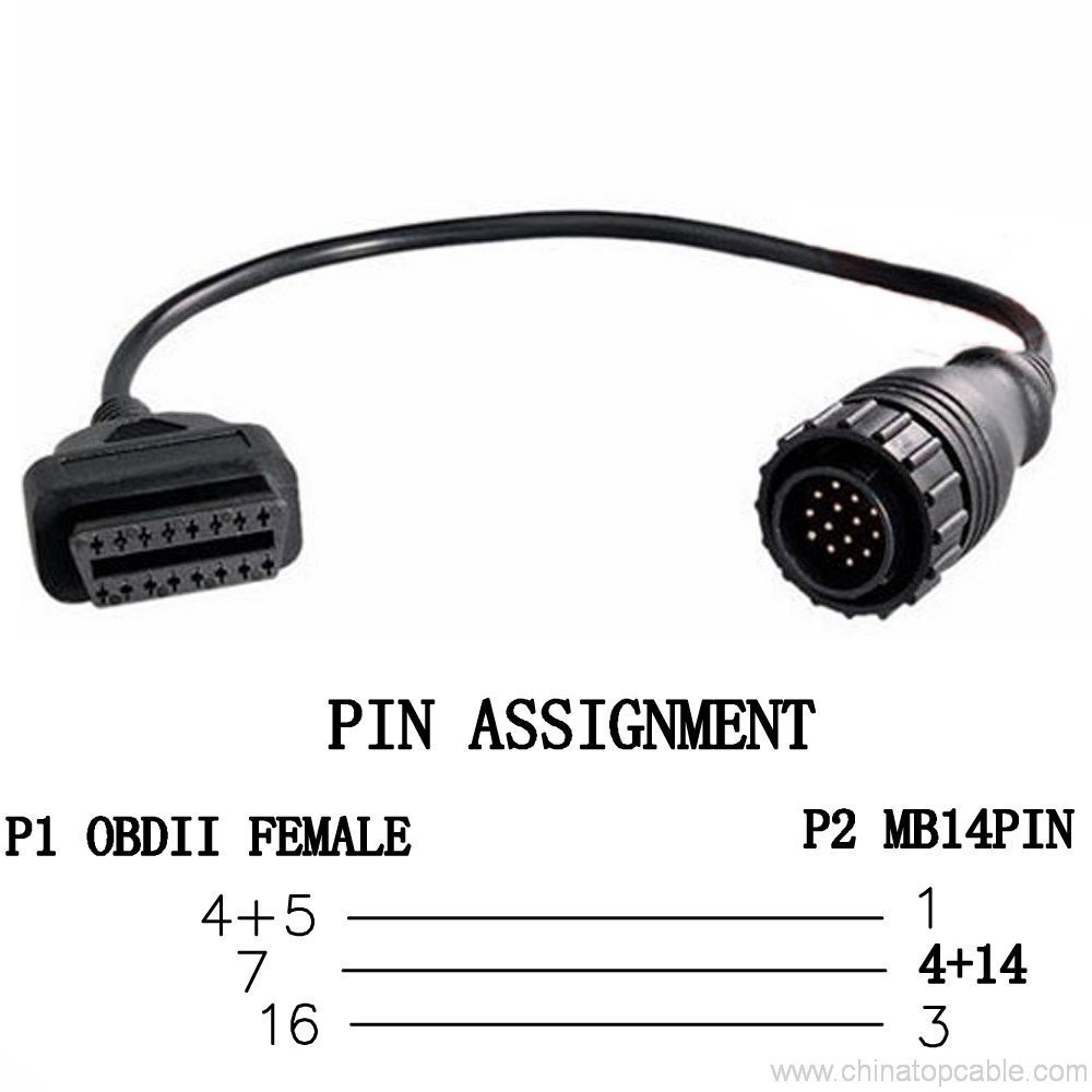
Nissian 14 Pino – 16Pino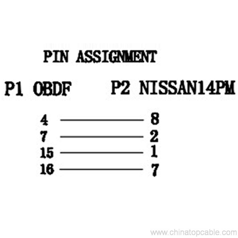
GM12 PIN-16PIN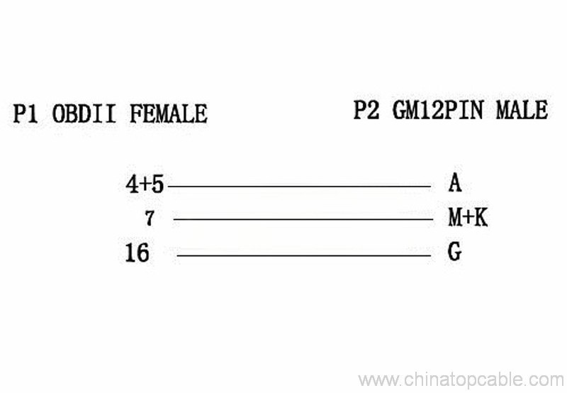
PIN DB9-16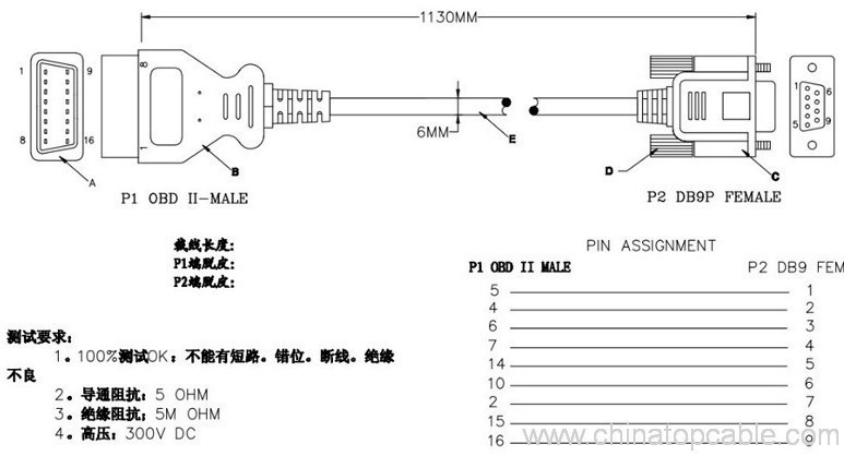
iveco 38 pines -16 Pino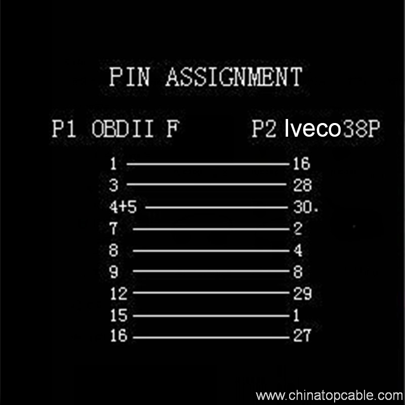
decreto 3 Pino – 16 Pino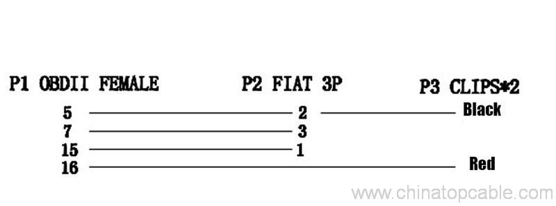
Toyato 22 pines – 16 Pino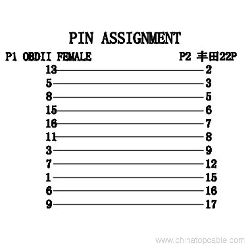
KIA 20 Pino – 16 Pino
Audi 2×2 – 16 Pino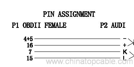
Benz 38 Pino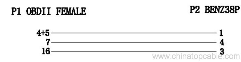
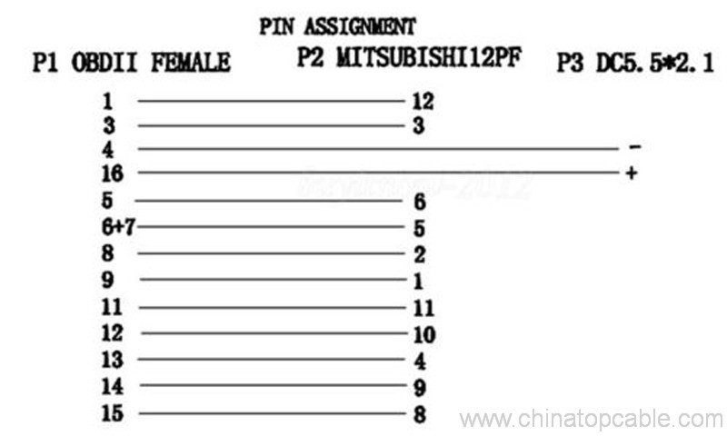
Mitsubishi 12 Pino – 16Pino
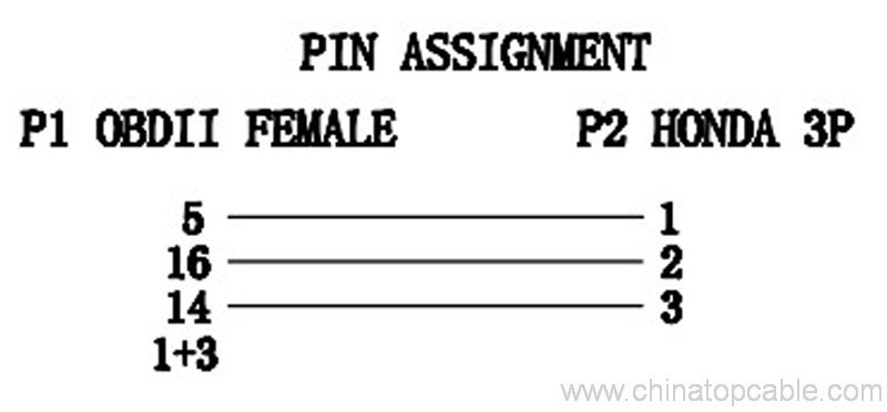
Honda 3 pines – 16Pino
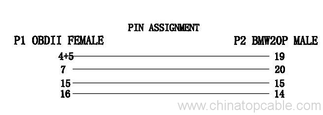
BMW 20 PIN – 3 Pino
Subaru 9 Pino – 16 Pino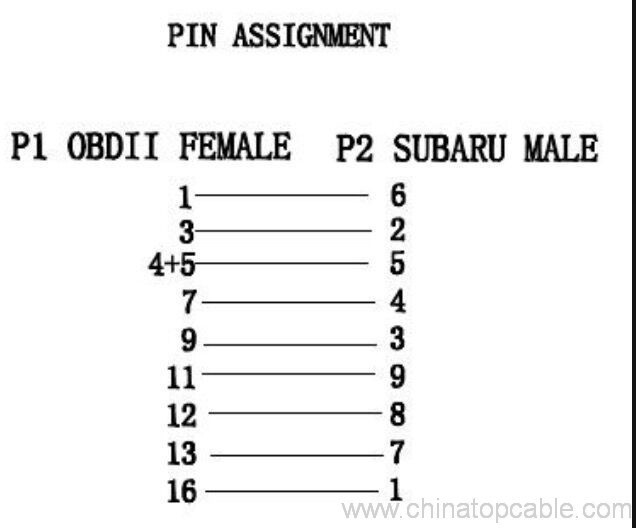
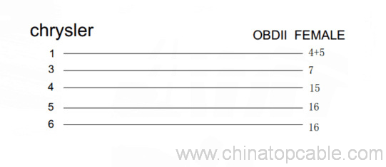
Chrysler 6 Pino