OBD2 Pabaiga atidaryta & išplėsti kabelio kaiščio priskyrimą ,prašome paspausti čia
Standartinis OBD2 pinout
Rūgštusis:Wiki
Režimai
Yra 10 veikimo būdai, aprašyti naujausiame OBD-II standarte SAE J1979. Jie yra tokie::
| Režimu (Hex) | Aprašymas |
|---|---|
| 01 | Rodyti dabartinius duomenis |
| 02 | Rodyti fiksavimo rėmelio duomenis |
| 03 | Rodyti saugomus diagnostikos problemų kodus |
| 04 | Išvalyti diagnostikos trikčių kodus ir saugomas reikšmes |
| 05 | Bandymo rezultatai, deguonies jutiklio stebėjimas (tik ne CAN) |
| 06 | Bandymo rezultatai, kitos sudedamosios dalies ir (arba) sistemos stebėjimas (Bandymo rezultatai, deguonies jutiklio stebėjimas tik CAN) |
| 07 | Rodyti laukiančius diagnostikos problemų kodus (aptinkamas per dabartinį arba paskutinį važiavimo ciklą) |
| 08 | Riedmens komponento ir (arba) sistemos valdymo veikimas |
| 09 | Prašyti transporto priemonės informacijos |
| 0A | Nuolatinis Diagnostiniai problemų kodai (Dtcs) (Išvalyti DTCs) |
Transporto priemonių gamintojai neprivalo palaikyti visų režimų. Kiekvienas gamintojas gali nustatyti papildomus režimus, #9 (pvz.: Režimu 22 kaip apibrėžta SAE J2190 Ford/GM, Režimu 21 dėl Toyota) kitai informacijai, pvz.,. traukos baterijos įtampą hibridinė elektra varoma transporto priemonė (Hev (Hev)).[2]
Standartiniai PID
Toliau pateiktoje lentelėje nurodyti standartiniai BDS II PPĮ, kaip apibrėžta SAE J1979. Laukiamas atsakas į kiekvieną PID pateikiamas, informacija apie tai, kaip atsakymą paversti prasmingais duomenimis. Vėl, ne visos transporto priemonės palaikys visus BĮD ir gali būti gamintojo nustatytų pasirinktinių PID, kurie nėra apibrėžti BDS II standarte.
Turìkite u3/4ra¹yti 1 ir 2 iš esmės yra identiškos, išskyrus tą režimą 1 teikia naujausią informaciją, kadangi režimas 2 pateikiama tų pačių duomenų, kurių buvo imtasi tuo metu, kai buvo nustatytas paskutinis diagnostikos trikties kodas, momentinė kopija. Išimtys yra PID 01, , kuri galima tik režimu 1, ir PID 02, , kuri galima tik režimu 2. Jei režimas 2 Pid 02 grąžina nulį, tada nėra momentinės kopijos ir visų kitų režimų 2 duomenys yra beprasmiai.
Naudojant bitų koduotą notaciją, kiekiai, pavyzdžiui, C4 reiškia bitų 4 iš duomenų baitų C. Kiekvienas bitas yra 0 į 7, Taigi 7 yra svarbiausias bitų ir 0 yra mažiausiai reikšmingas bitų.
| A | B | C | D | ||||||||||||||||||||||||||||
| A7 A7 (Os) | A6 | A5 (1809) | A4 | A3 A3 (199 | A2 -- Viešbučiai | A1 -- | A0 (Netoli viešbučio) | B7 (Netoli viešbučio b7 | B6 (Netoli viešbučio) | B5 (Netoli viešbučio) | B4 (B4) | B3 (Netoli viešbučio) | B2 | B1 (Netoli viešbučio) | B0 (Netoli viešbučio b0 | C7 (05 | C6 (Netoli viešbučio) | C5 (15 | C4 (C4) | C3 (3 | C2 (2 03 | C1 (C1) | C0 (C0) | D7 (D7) | D6 (D6) | D5 (D5) | D4 (D4) | D3 (D3) | D2 (D2) | D1 (D1) | D0 (D0) |
Režimu 01
| Pid (Hex) |
Pid (Gruodis) |
Grąžinti duomenų baitai | Aprašymas | Min. reikšmė | Maksimali vertė | Vienetų | Formulė[a] |
|---|---|---|---|---|---|---|---|
| 00 | 0 | 4 | PpD palaikomi [01 – 20] | Šiek tiek užkoduotas [A7. D0 (D0)] == [PID $01..PID (01..PID) $20] Žr. | |||
| 01 | 1 | 4 | Stebėti būseną nuo DTCs išvalyti. (Apima gedimo indikatoriaus lempą (Mil) dtšt sumą ir skaičių.) | Šiek tiek užkoduotas. Žr. | |||
| 02 | 2 | 2 | Užšaldyti DTK | ||||
| 03 | 3 | 2 | Degalų sistemos būsena | Šiek tiek užkoduotas. Žr. | |||
| 04 | 4 | 1 | Apskaičiuota variklio apkrova | 0 | 100 | % | {\ekrano stilius {\tfrac (-us) {100}{255}}A} (arba {\ekrano stilius {\tfrac (-us) {A}{2.55}}}) |
| 05 | 5 | 1 | Variklio aušalo temperatūra | -40 | 215 | ° C | {\ekrano stilius A-40} |
| 06 | 6 | 1 | Trumpalaikis kuro apdaila-Bankas 1 | -100 (Sumažinti degalų: Per daug turtingas) | 99.2 (Pridėti kuro: Per liesos) | % |
{\ekrano stilius {\frac ( {100}{128}}A-100 (100)}
(arba {\ekrano stilius {\tfrac (-us) {A}{1.28}}-100} ) |
| 07 | 7 | 1 | Ilgalaikis kuro apdaila - Bankas 1 | ||||
| 08 | 8 | 1 | Trumpalaikis kuro apdaila-Bankas 2 | ||||
| 09 | 9 | 1 | Ilgalaikis kuro apdaila - Bankas 2 | ||||
| 0A | 10 | 1 | Degalų slėgis (matuoklio slėgis) | 0 | 765 | Kpa | {\displaystyle 3A (Rodyti panašias apgyvendinimo įstaigas)} |
| 0B | 11 | 1 | Įsiurbimo kolektoriaus absoliutusis slėgis | 0 | 255 | Kpa | {\A ekrano stilius} |
| 0C | 12 | 2 | Variklio aps./min. | 0 | 16,383.75 | Rpm | {\ekrano stilius {\frac ( {256A+B (A+B)}{4}}} |
| 0D | 13 | 1 | Transporto priemonės greitis | 0 | 255 | km/h | {\A ekrano stilius} |
| 0E | 14 | 1 | Laiko iš anksto | -64 | 63.5 | ° before TDC | {\ekrano stilius {\frac ( {A}{2}}-64} |
| 0F | 15 | 1 | Intake air temperature | -40 | 215 | ° C | {\ekrano stilius A-40} |
| 10 | 16 | 2 | MAF air flow rate | 0 | 655.35 | grams/sec | {\ekrano stilius {\frac ( {256A+B (A+B)}{100}}} |
| 11 | 17 | 1 | Throttle position | 0 | 100 | % | {\ekrano stilius {\tfrac (-us) {100}{255}}A} |
| 12 | 18 | 1 | Commanded secondary air status | Šiek tiek užkoduotas. Žr. | |||
| 13 | 19 | 1 | Oxygen sensors present (į 2 banks) | [A0..A3] == Bank 1, Sensors 1-4. [A4..A7] == Bank 2… | |||
| 14 | 20 | 2 | Oxygen Sensor 1 A: Įtampos B: Short term fuel trim |
0 -100 |
1.275 99.2 |
volts% |
{\ekrano stilius {\frac ( {A}{200}}}
{\ekrano stilius {\frac ( {100}{128}}B-100}
(if B==$FF, sensor is not used in trim calculation) |
| 15 | 21 | 2 | Oxygen Sensor 2 A: Įtampos B: Short term fuel trim |
||||
| 16 | 22 | 2 | Oxygen Sensor 3 A: Įtampos B: Short term fuel trim |
||||
| 17 | 23 | 2 | Oxygen Sensor 4 A: Įtampos B: Short term fuel trim |
||||
| 18 | 24 | 2 | Oxygen Sensor 5 A: Įtampos B: Short term fuel trim |
||||
| 19 | 25 | 2 | Oxygen Sensor 6 A: Įtampos B: Short term fuel trim |
||||
| 1A | 26 | 2 | Oxygen Sensor 7 A: Įtampos B: Short term fuel trim |
||||
| 1B | 27 | 2 | Oxygen Sensor 8 A: Įtampos B: Short term fuel trim |
||||
| 1C | 28 | 1 | OBD standards this vehicle conforms to | Šiek tiek užkoduotas. Žr. | |||
| 1D | 29 | 1 | Oxygen sensors present (į 4 banks) | Similar to PID 13, but [A0..A7] == [B1S1, B1S2, B2S1, B2S2, B3S1, B3S2, B4S1, B4S2] | |||
| 1E | 30 | 1 | Auxiliary input status | A0 == Power Take Off (PTO) status (1 == active) [A1..A7] not used |
|||
| 1F | 31 | 2 | Run time since engine start | 0 | 65,535 | seconds | {\displaystyle 256A+B} |
| 20 | 32 | 4 | PpD palaikomi [21 – 40] | Šiek tiek užkoduotas [A7. D0 (D0)] == [PID $21..PID $40] Žr. | |||
| 21 | 33 | 2 | Distance traveled with malfunction indicator lamp (Mil) dėl | 0 | 65,535 | km | {\displaystyle 256A+B} |
| 22 | 34 | 2 | Fuel Rail Pressure (relative to manifold vacuum) | 0 | 5177.265 | Kpa | {\ekrano stilius 0.079(256A+B (A+B))} |
| 23 | 35 | 2 | Fuel Rail Gauge Pressure (diesel, or gasoline direct injection) | 0 | 655,350 | Kpa | {\ekrano stilius 10(256A+B (A+B))} |
| 24 | 36 | 4 | Oxygen Sensor 1 AB: Fuel–Air Equivalence Ratio CD: Įtampos |
0 0 |
< 2 < 8 |
ratio V |
{\ekrano stilius {\frac ( {2}{65536}}(256A+B (A+B))}
{\ekrano stilius {\frac ( {8}{65536}}(256C+D)}
|
| 25 | 37 | 4 | Oxygen Sensor 2 AB: Fuel–Air Equivalence Ratio CD: Įtampos |
||||
| 26 | 38 | 4 | Oxygen Sensor 3 AB: Fuel–Air Equivalence Ratio CD: Įtampos |
||||
| 27 | 39 | 4 | Oxygen Sensor 4 AB: Fuel–Air Equivalence Ratio CD: Įtampos |
||||
| 28 | 40 | 4 | Oxygen Sensor 5 AB: Fuel–Air Equivalence Ratio CD: Įtampos |
||||
| 29 | 41 | 4 | Oxygen Sensor 6 AB: Fuel–Air Equivalence Ratio CD: Įtampos |
||||
| 2A | 42 | 4 | Oxygen Sensor 7 AB: Fuel–Air Equivalence Ratio CD: Įtampos |
||||
| 2B | 43 | 4 | Oxygen Sensor 8 AB: Fuel–Air Equivalence Ratio CD: Įtampos |
||||
| 2C | 44 | 1 | Commanded EGR | 0 | 100 | % | {\ekrano stilius {\tfrac (-us) {100}{255}}A} |
| 2D | 45 | 1 | EGR Error | -100 | 99.2 | % | {\ekrano stilius {\tfrac (-us) {100}{128}}A-100 (100)} |
| 2E | 46 | 1 | Commanded evaporative purge | 0 | 100 | % | {\ekrano stilius {\tfrac (-us) {100}{255}}A} |
| 2F | 47 | 1 | Fuel Tank Level Input | 0 | 100 | % | {\ekrano stilius {\tfrac (-us) {100}{255}}A} |
| 30 | 48 | 1 | Warm-ups since codes cleared | 0 | 255 | count | {\A ekrano stilius} |
| 31 | 49 | 2 | Distance traveled since codes cleared | 0 | 65,535 | km | {\displaystyle 256A+B} |
| 32 | 50 | 2 | Evap. System Vapor Pressure | -8,192 | 8191.75 | Pa | {\ekrano stilius {\frac ( {256A+B (A+B)}{4}}}(AB is two’s complement signed)[3] |
| 33 | 51 | 1 | Absolute Barometric Pressure | 0 | 255 | Kpa | {\A ekrano stilius} |
| 34 | 52 | 4 | Oxygen Sensor 1 AB: Fuel–Air Equivalence Ratio CD: Srovė |
0 -128 |
< 2 <128 |
ratio mA |
{\ekrano stilius {\frac ( {2}{65536}}(256A+B (A+B))}
{\ekrano stilius {\frac ( {256C+D}{256}}-128}
arba {\displaystyle C+{\frac ( {D}{256}}-128} |
| 35 | 53 | 4 | Oxygen Sensor 2 AB: Fuel–Air Equivalence Ratio CD: Srovė |
||||
| 36 | 54 | 4 | Oxygen Sensor 3 AB: Fuel–Air Equivalence Ratio CD: Srovė |
||||
| 37 | 55 | 4 | Oxygen Sensor 4 AB: Fuel–Air Equivalence Ratio CD: Srovė |
||||
| 38 | 56 | 4 | Oxygen Sensor 5 AB: Fuel–Air Equivalence Ratio CD: Srovė |
||||
| 39 | 57 | 4 | Oxygen Sensor 6 AB: Fuel–Air Equivalence Ratio CD: Srovė |
||||
| 3A | 58 | 4 | Oxygen Sensor 7 AB: Fuel–Air Equivalence Ratio CD: Srovė |
||||
| 3B | 59 | 4 | Oxygen Sensor 8 AB: Fuel–Air Equivalence Ratio CD: Srovė |
||||
| 3C | 60 | 2 | Catalyst Temperature: Bank 1, Sensor 1 | -40 | 6,513.5 | ° C | {\ekrano stilius {\frac ( {256A+B (A+B)}{10}}-40} |
| 3D | 61 | 2 | Catalyst Temperature: Bank 2, Sensor 1 | ||||
| 3E | 62 | 2 | Catalyst Temperature: Bank 1, Sensor 2 | ||||
| 3F | 63 | 2 | Catalyst Temperature: Bank 2, Sensor 2 | ||||
| 40 | 64 | 4 | PpD palaikomi [41 – 60] | Šiek tiek užkoduotas [A7. D0 (D0)] == [PID $41..PID $60] Žr. | |||
| 41 | 65 | 4 | Monitor status this drive cycle | Šiek tiek užkoduotas. Žr. | |||
| 42 | 66 | 2 | Control module voltage | 0 | 65.535 | V | {\ekrano stilius {\frac ( {256A+B (A+B)}{1000}}} |
| 43 | 67 | 2 | Absolute load value | 0 | 25,700 | % | {\ekrano stilius {\tfrac (-us) {100}{255}}(256A+B (A+B))} |
| 44 | 68 | 2 | Fuel–Air commanded equivalence ratio | 0 | < 2 | ratio | {\ekrano stilius {\tfrac (-us) {2}{65536}}(256A+B (A+B))} |
| 45 | 69 | 1 | Relative throttle position | 0 | 100 | % | {\ekrano stilius {\tfrac (-us) {100}{255}}A} |
| 46 | 70 | 1 | Ambient air temperature | -40 | 215 | ° C | {\ekrano stilius A-40} |
| 47 | 71 | 1 | Absolute throttle position B | 0 | 100 | % | {\ekrano stilius {\frac ( {100}{255}}A} |
| 48 | 72 | 1 | Absolute throttle position C | ||||
| 49 | 73 | 1 | Accelerator pedal position D | ||||
| 4A | 74 | 1 | Accelerator pedal position E | ||||
| 4B | 75 | 1 | Accelerator pedal position F | ||||
| 4C | 76 | 1 | Commanded throttle actuator | ||||
| 4D | 77 | 2 | Time run with MIL on | 0 | 65,535 | minutes | {\displaystyle 256A+B} |
| 4E | 78 | 2 | Time since trouble codes cleared | ||||
| 4F | 79 | 4 | Maximum value for Fuel–Air equivalence ratio, oxygen sensor voltage, oxygen sensor current, and intake manifold absolute pressure | 0, 0, 0, 0 | 255, 255, 255, 2550 | ratio, V, mA, Kpa | A, B, C, D*10 |
| 50 | 80 | 4 | Maximum value for air flow rate from mass air flow sensor | 0 | 2550 | g/s | A*10, B, C, and D are reserved for future use |
| 51 | 81 | 1 | Fuel Type | From fuel type table see below | |||
| 52 | 82 | 1 | Ethanol fuel % | 0 | 100 | % | {\ekrano stilius {\tfrac (-us) {100}{255}}A} |
| 53 | 83 | 2 | Absolute Evap system Vapor Pressure | 0 | 327.675 | Kpa | {\ekrano stilius {\frac ( {256A+B (A+B)}{200}}} |
| 54 | 84 | 2 | Evap system vapor pressure | -32,767 | 32,768 | Pa | ((A*256)+B)-32767 |
| 55 | 85 | 2 | Short term secondary oxygen sensor trim, A: bank 1, B: bank 3 | -100 | 99.2 | % | {\ekrano stilius {\frac ( {100}{128}}A-100 (100)}{\ekrano stilius {\frac ( {100}{128}}B-100} |
| 56 | 86 | 2 | Long term secondary oxygen sensor trim, A: bank 1, B: bank 3 | ||||
| 57 | 87 | 2 | Short term secondary oxygen sensor trim, A: bank 2, B: bank 4 | ||||
| 58 | 88 | 2 | Long term secondary oxygen sensor trim, A: bank 2, B: bank 4 | ||||
| 59 | 89 | 2 | Fuel rail absolute pressure | 0 | 655,350 | Kpa | {\ekrano stilius 10(256A+B (A+B))} |
| 5A | 90 | 1 | Relative accelerator pedal position | 0 | 100 | % | {\ekrano stilius {\tfrac (-us) {100}{255}}A} |
| 5B | 91 | 1 | Hybrid battery pack remaining life | 0 | 100 | % | {\ekrano stilius {\tfrac (-us) {100}{255}}A} |
| 5C | 92 | 1 | Engine oil temperature | -40 | 210 | ° C | {\ekrano stilius A-40} |
| 5D | 93 | 2 | Fuel injection timing | -210.00 | 301.992 | ° | {\ekrano stilius {\frac ( {256A+B (A+B)}{128}}-210} |
| 5E | 94 | 2 | Engine fuel rate | 0 | 3276.75 | L/h | {\ekrano stilius {\frac ( {256A+B (A+B)}{20}}} |
| 5F | 95 | 1 | Emission requirements to which vehicle is designed | Bit Encoded | |||
| 60 | 96 | 4 | PpD palaikomi [61 – 80] | Šiek tiek užkoduotas [A7. D0 (D0)] == [PID $61..PID $80] Žr. | |||
| 61 | 97 | 1 | Driver’s demand engine – percent torque | -125 | 125 | % | A-125 |
| 62 | 98 | 1 | Actual engine – percent torque | -125 | 125 | % | A-125 |
| 63 | 99 | 2 | Engine reference torque | 0 | 65,535 | Nm | {\displaystyle 256A+B} |
| 64 | 100 | 5 | Engine percent torque data | -125 | 125 | % | A-125 Idle B-125 Engine point 1 C-125 Engine point 2 D-125 Engine point 3 E-125 Engine point 4 |
| 65 | 101 | 2 | Auxiliary input / output supported | Bit Encoded | |||
| 66 | 102 | 5 | Mass air flow sensor | ||||
| 67 | 103 | 3 | Variklio aušalo temperatūra | ||||
| 68 | 104 | 7 | Intake air temperature sensor | ||||
| 69 | 105 | 7 | Commanded EGR and EGR Error | ||||
| 6A | 106 | 5 | Commanded Diesel intake air flow control and relative intake air flow position | ||||
| 6B | 107 | 5 | Exhaust gas recirculation temperature | ||||
| 6C | 108 | 5 | Commanded throttle actuator control and relative throttle position | ||||
| 6D | 109 | 6 | Fuel pressure control system | ||||
| 6E | 110 | 5 | Injection pressure control system | ||||
| 6F | 111 | 3 | Turbocharger compressor inlet pressure | ||||
| 70 | 112 | 9 | Boost pressure control | ||||
| 71 | 113 | 5 | Variable Geometry turbo (VGT) control | ||||
| 72 | 114 | 5 | Wastegate control | ||||
| 73 | 115 | 5 | Exhaust pressure | ||||
| 74 | 116 | 5 | Turbocharger RPM | ||||
| 75 | 117 | 7 | Turbocharger temperature | ||||
| 76 | 118 | 7 | Turbocharger temperature | ||||
| 77 | 119 | 5 | Charge air cooler temperature (CACT) | ||||
| 78 | 120 | 9 | Exhaust Gas temperature (EGT) Bank 1 | Special PID. Žr. | |||
| 79 | 121 | 9 | Exhaust Gas temperature (EGT) Bank 2 | Special PID. Žr. | |||
| 7A | 122 | 7 | Diesel particulate filter (DPF) | ||||
| 7B | 123 | 7 | Diesel particulate filter (DPF) | ||||
| 7C | 124 | 9 | Diesel Particulate filter (DPF) temperature | ||||
| 7D | 125 | 1 | NOx NTE (Not-To-Exceed) control area status | ||||
| 7E | 126 | 1 | PM NTE (Not-To-Exceed) control area status | ||||
| 7F | 127 | 13 | Engine run time | ||||
| 80 | 128 | 4 | PpD palaikomi [81 – A0 (Netoli viešbučio)] | Šiek tiek užkoduotas [A7. D0 (D0)] == [PID $81..PID $A0] Žr. | |||
| 81 | 129 | 21 | Engine run time for Auxiliary Emissions Control Device(AECD) | ||||
| 82 | 130 | 21 | Engine run time for Auxiliary Emissions Control Device(AECD) | ||||
| 83 | 131 | 5 | NOx sensor | ||||
| 84 | 132 | Manifold surface temperature | |||||
| 85 | 133 | NOx reagent system | |||||
| 86 | 134 | Particulate matter (PM) sensor | |||||
| 87 | 135 | Įsiurbimo kolektoriaus absoliutusis slėgis | |||||
| A0 (Netoli viešbučio) | 160 | 4 | PpD palaikomi [A1 -- – C0 (C0)] | Šiek tiek užkoduotas [A7. D0 (D0)] == [PID $A1..PID $C0] Žr. | |||
| C0 (C0) | 192 | 4 | PpD palaikomi [C1 (C1) – E0] | Šiek tiek užkoduotas [A7. D0 (D0)] == [PID $C1..PID $E0] Žr. | |||
| C3 (3 | 195 | ? | ? | ? | ? | ? | Returns numerous data, including Drive Condition ID and Engine Speed* |
| C4 (C4) | 196 | ? | ? | ? | ? | ? | B5 is Engine Idle Request B6 is Engine Stop Request* |
| Pid (Hex) |
Pid (Gruodis) |
Grąžinti duomenų baitai | Aprašymas | Min. reikšmė | Maksimali vertė | Vienetų | Formulė[a] |


Režimu 02[edit]
Režimu 02 accepts the same PIDs as mode 01, with the same meaning, but information given is from when the freeze frame was created.
You have to send the frame number in the data section of the message.
| Pid (Hex) |
Grąžinti duomenų baitai | Aprašymas | Min. reikšmė | Maksimali vertė | Vienetų | Formulė[a] |
|---|---|---|---|---|---|---|
| 02 | 2 | DTC that caused freeze frame to be stored. | BCD encoded. Decoded as in mode 3 |
Režimu 03
| Pid (Hex) |
Grąžinti duomenų baitai | Aprašymas | Min. reikšmė | Maksimali vertė | Vienetų | Formulė[a] |
|---|---|---|---|---|---|---|
| N/A | n*6 | Request trouble codes | 3 codes per message frame. Žr. |
Režimu 04[edit]
| Pid (Hex) |
Grąžinti duomenų baitai | Aprašymas | Min. reikšmė | Maksimali vertė | Vienetų | Formulė[a] |
|---|---|---|---|---|---|---|
| N/A | 0 | Clear trouble codes / Malfunction indicator lamp (Mil) / Check engine light | Clears all stored trouble codes and turns the MIL off. |
Režimu 05
| Pid (Hex) |
Grąžinti duomenų baitai | Aprašymas | Min. reikšmė | Maksimali vertė | Vienetų | Formulė[a] |
|---|---|---|---|---|---|---|
| 0100 | OBD Monitor IDs supported ($01 – $20) | |||||
| 0101 | O2 Sensor Monitor Bank 1 Sensor 1 | 0.00 | 1.275 | volts | 0.005 Rich to lean sensor threshold voltage | |
| 0102 | O2 Sensor Monitor Bank 1 Sensor 2 | 0.00 | 1.275 | volts | 0.005 Rich to lean sensor threshold voltage | |
| 0103 | O2 Sensor Monitor Bank 1 Sensor 3 | 0.00 | 1.275 | volts | 0.005 Rich to lean sensor threshold voltage | |
| 0104 | O2 Sensor Monitor Bank 1 Sensor 4 | 0.00 | 1.275 | volts | 0.005 Rich to lean sensor threshold voltage | |
| 0105 | O2 Sensor Monitor Bank 2 Sensor 1 | 0.00 | 1.275 | volts | 0.005 Rich to lean sensor threshold voltage | |
| 0106 | O2 Sensor Monitor Bank 2 Sensor 2 | 0.00 | 1.275 | volts | 0.005 Rich to lean sensor threshold voltage | |
| 0107 | O2 Sensor Monitor Bank 2 Sensor 3 | 0.00 | 1.275 | volts | 0.005 Rich to lean sensor threshold voltage | |
| 0108 | O2 Sensor Monitor Bank 2 Sensor 4 | 0.00 | 1.275 | volts | 0.005 Rich to lean sensor threshold voltage | |
| 0109 | O2 Sensor Monitor Bank 3 Sensor 1 | 0.00 | 1.275 | volts | 0.005 Rich to lean sensor threshold voltage | |
| 010A | O2 Sensor Monitor Bank 3 Sensor 2 | 0.00 | 1.275 | volts | 0.005 Rich to lean sensor threshold voltage | |
| 010B | O2 Sensor Monitor Bank 3 Sensor 3 | 0.00 | 1.275 | volts | 0.005 Rich to lean sensor threshold voltage | |
| 010C | O2 Sensor Monitor Bank 3 Sensor 4 | 0.00 | 1.275 | volts | 0.005 Rich to lean sensor threshold voltage | |
| 010D | O2 Sensor Monitor Bank 4 Sensor 1 | 0.00 | 1.275 | volts | 0.005 Rich to lean sensor threshold voltage | |
| 010E | O2 Sensor Monitor Bank 4 Sensor 2 | 0.00 | 1.275 | volts | 0.005 Rich to lean sensor threshold voltage | |
| 010F | O2 Sensor Monitor Bank 4 Sensor 3 | 0.00 | 1.275 | volts | 0.005 Rich to lean sensor threshold voltage | |
| 0110 | O2 Sensor Monitor Bank 4 Sensor 4 | 0.00 | 1.275 | volts | 0.005 Rich to lean sensor threshold voltage | |
| 0201 | O2 Sensor Monitor Bank 1 Sensor 1 | 0.00 | 1.275 | volts | 0.005 Lean to Rich sensor threshold voltage | |
| 0202 | O2 Sensor Monitor Bank 1 Sensor 2 | 0.00 | 1.275 | volts | 0.005 Lean to Rich sensor threshold voltage | |
| 0203 | O2 Sensor Monitor Bank 1 Sensor 3 | 0.00 | 1.275 | volts | 0.005 Lean to Rich sensor threshold voltage | |
| 0204 | O2 Sensor Monitor Bank 1 Sensor 4 | 0.00 | 1.275 | volts | 0.005 Lean to Rich sensor threshold voltage | |
| 0205 | O2 Sensor Monitor Bank 2 Sensor 1 | 0.00 | 1.275 | volts | 0.005 Lean to Rich sensor threshold voltage | |
| 0206 | O2 Sensor Monitor Bank 2 Sensor 2 | 0.00 | 1.275 | volts | 0.005 Lean to Rich sensor threshold voltage | |
| 0207 | O2 Sensor Monitor Bank 2 Sensor 3 | 0.00 | 1.275 | volts | 0.005 Lean to Rich sensor threshold voltage | |
| 0208 | O2 Sensor Monitor Bank 2 Sensor 4 | 0.00 | 1.275 | volts | 0.005 Lean to Rich sensor threshold voltage | |
| 0209 | O2 Sensor Monitor Bank 3 Sensor 1 | 0.00 | 1.275 | volts | 0.005 Lean to Rich sensor threshold voltage | |
| 020A | O2 Sensor Monitor Bank 3 Sensor 2 | 0.00 | 1.275 | volts | 0.005 Lean to Rich sensor threshold voltage | |
| 020B | O2 Sensor Monitor Bank 3 Sensor 3 | 0.00 | 1.275 | volts | 0.005 Lean to Rich sensor threshold voltage | |
| 020C | O2 Sensor Monitor Bank 3 Sensor 4 | 0.00 | 1.275 | volts | 0.005 Lean to Rich sensor threshold voltage | |
| 020D | O2 Sensor Monitor Bank 4 Sensor 1 | 0.00 | 1.275 | volts | 0.005 Lean to Rich sensor threshold voltage | |
| 020E | O2 Sensor Monitor Bank 4 Sensor 2 | 0.00 | 1.275 | volts | 0.005 Lean to Rich sensor threshold voltage | |
| 020F | O2 Sensor Monitor Bank 4 Sensor 3 | 0.00 | 1.275 | volts | 0.005 Lean to Rich sensor threshold voltage | |
| 0210 | O2 Sensor Monitor Bank 4 Sensor 4 | 0.00 | 1.275 | volts | 0.005 Lean to Rich sensor threshold voltage | |
| Pid (Hex) |
Grąžinti duomenų baitai | Aprašymas | Min. reikšmė | Maksimali vertė | Vienetų | Formulė[a] |
Režimu 09
| Pid (Hex) |
Grąžinti duomenų baitai | Aprašymas | Min. reikšmė | Maksimali vertė | Vienetų | Formulė[a] |
|---|---|---|---|---|---|---|
| 00 | 4 | Režimu 9 supported PIDs (01 į 20) | Šiek tiek užkoduotas. [A7. D0 (D0)] = [PID $01..PID (01..PID) $20] Žr. | |||
| 01 | 1 | VIN Message Count in PID 02. Only for ISO 9141-2, ISO 14230-4 and SAE J1850. | Usually value will be 5. | |||
| 02 | 17 | Vehicle Identification Number (VIN) | 17-char VIN, ASCII-encoded and left-padded with null chars (0x00) if needed to. | |||
| 03 | 1 | Calibration ID message count for PID 04. Only for ISO 9141-2, ISO 14230-4 and SAE J1850. | It will be a multiple of 4 (4 messages are needed for each ID). | |||
| 04 | 16,32,48,64.. | Calibration ID | Iki 16 ASCII chars. Data bytes not used will be reported as null bytes (0x00). Several CALID can be outputed (16 bytes each) | |||
| 05 | 1 | Calibration verification numbers (CVN) message count for PID 06. Only for ISO 9141-2, ISO 14230-4 and SAE J1850. | ||||
| 06 | 4,8,12,16 | Calibration Verification Numbers (CVN) Several CVN can be outputed (4 bytes each) the number of CVN and CALID must match | Raw data left-padded with null characters (0x00). Usually displayed as hex string. | |||
| 07 | 1 | In-use performance tracking message count for PID 08 ir 0B. Only for ISO 9141-2, ISO 14230-4 and SAE J1850. | 8 | 10 | 8 if sixteen (16) values are required to be reported, 9 if eighteen (18) values are required to be reported, ir 10 if twenty (20) values are required to be reported (one message reports two values, each one consisting in two bytes). | |
| 08 | 4 | In-use performance tracking for spark ignition vehicles | 4 arba 5 messages, each one containing 4 bytes (two values). Žr. | |||
| 09 | 1 | ECU name message count for PID 0A | ||||
| 0A | 20 | ECU name | ASCII-coded. Right-padded with null chars (0x00). | |||
| 0B | 4 | In-use performance tracking for compression ignition vehicles | 5 messages, each one containing 4 bytes (two values). Žr. | |||
| Pid (Hex) |
Grąžinti duomenų baitai | Aprašymas | Min. reikšmė | Maksimali vertė | Vienetų | Formulė[a] |
Bitwise encoded PIDs
Some of the PIDs in the above table cannot be explained with a simple formula. A more elaborate explanation of these data is provided here:
Režimu 1 Pid 00
A request for this PID returns 4 bytes of data. Each bit, from MSB į LSB, represents one of the next 32 PIDs and is giving information about if it is supported.
For example, if the car response is BE1FA813, it can be decoded like this:
| Hexadecimal | B | E | 1 | F | A | 8 | 1 | 3 | ||||||||||||||||||||||||
|---|---|---|---|---|---|---|---|---|---|---|---|---|---|---|---|---|---|---|---|---|---|---|---|---|---|---|---|---|---|---|---|---|
| Binary | 1 | 0 | 1 | 1 | 1 | 1 | 1 | 0 | 0 | 0 | 0 | 1 | 1 | 1 | 1 | 1 | 1 | 0 | 1 | 0 | 1 | 0 | 0 | 0 | 0 | 0 | 0 | 1 | 0 | 0 | 1 | 1 |
| Palaiko? | taip | No | taip | taip | taip | taip | taip | No | No | No | No | taip | taip | taip | taip | taip | taip | No | taip | No | taip | No | No | No | No | No | No | taip | No | No | taip | taip |
| PID number | 01 | 02 | 03 | 04 | 05 | 06 | 07 | 08 | 09 | 0A | 0B | 0C | 0D | 0E | 0F | 10 | 11 | 12 | 13 | 14 | 15 | 16 | 17 | 18 | 19 | 1A | 1B | 1C | 1D | 1E | 1F | 20 |
So, supported PIDs are: 01, 03, 04, 05, 06, 07, 0C, 0D, 0E, 0F, 10, 11, 13, 15, 1C, 1F ir 20
Režimu 1 Pid 01
A request for this PID returns 4 bytes of data, labeled A B C and D.
The first byte(A) contains two pieces of information. Bit A7 A7 (Os) (MSB of byte A, the first byte) indicates whether or not the MIL (check engine light) is illuminated. Bits A6 through A0 (Netoli viešbučio)represent the number of diagnostic trouble codes currently flagged in the ECU.
The second, third, and fourth bytes(B, C and D) give information about the availability and completeness of certain on-board tests. Note that test availability is indicated by set (1) bit and completeness is indicated by reset (0) šiek tiek.
| Bit | Pavadinimas | Definition |
|---|---|---|
| A7 A7 (Os) | Mil | Off or On, indicates if the CEL/MIL is on (or should be on) |
| A6–A0 (Netoli viešbučio) | DTC_CNT | Number of confirmed emissions-related DTCs available for display. |
| B7 (Netoli viešbučio b7 | RESERVED | Reserved (should be 0) |
| B3 (Netoli viešbučio) | NO NAME | 0 = Spark ignition monitors supported (pvz.. Otto or Wankel engines) 1 = Compression ignition monitors supported (pvz.. Diesel engines) |
Here are the common bit B definitions, they are test based.
| Test available | Test incomplete | |
|---|---|---|
| Components | B2 | B6 (Netoli viešbučio) |
| Fuel System | B1 (Netoli viešbučio) | B5 (Netoli viešbučio) |
| Misfire | B0 (Netoli viešbučio b0 | B4 (B4) |
The third and fourth bytes are to be interpreted differently depending on if the engine is spark Uždegimo (pvz.. Otto or Wankel engines) arba compression ignition (pvz.. Diesel engines). In the second (B) byte, šiek tiek 3 indicates how to interpret the C and D bytes, with 0 being spark (Otto or Wankel) ir 1 (set) being compression (Diesel).
The bytes C and D for spark ignition monitors (pvz.. Otto or Wankel engines):
| Test available | Test incomplete | |
|---|---|---|
| EGR System | C7 (05 | D7 (D7) |
| Oxygen Sensor Heater | C6 (Netoli viešbučio) | D6 (D6) |
| Oxygen Sensor | C5 (15 | D5 (D5) |
| A/C Refrigerant | C4 (C4) | D4 (D4) |
| Secondary Air System | C3 (3 | D3 (D3) |
| Evaporative System | C2 (2 03 | D2 (D2) |
| Heated Catalyst | C1 (C1) | D1 (D1) |
| Catalyst | C0 (C0) | D0 (D0) |
And the bytes C and D for compression ignition monitors (Diesel engines):
| Test available | Test incomplete | |
|---|---|---|
| EGR and/or VVT System | C7 (05 | D7 (D7) |
| PM filter monitoring | C6 (Netoli viešbučio) | D6 (D6) |
| Exhaust Gas Sensor | C5 (15 | D5 (D5) |
| – Reserved – | C4 (C4) | D4 (D4) |
| Boost Pressure | C3 (3 | D3 (D3) |
| – Reserved – | C2 (2 03 | D2 (D2) |
| NOx/SCR Monitor | C1 (C1) | D1 (D1) |
| NMHC Catalyst[a] | C0 (C0) | D0 (D0) |
- Jump up^ NMHC may stand for Non-Methane HydroCarbons, but J1979 does not enlighten us. The translation would be the ammonia sensor in the SCR catalyst.
Režimu 1 Pid 41
A request for this PID returns 4 bytes of data. The first byte is always zero. The second, third, and fourth bytes give information about the availability and completeness of certain on-board tests. As with PID 01, the third and fourth bytes are to be interpreted differently depending on the ignition type (B3 (Netoli viešbučio)) – with 0 being spark and 1 (set) being compression. Note again that test availability is represented by a set (1) bit and completeness is represented by a reset (0) šiek tiek.
Here are the common bit B definitions, they are test based.
| Test available | Test incomplete | |
|---|---|---|
| Components | B2 | B6 (Netoli viešbučio) |
| Fuel System | B1 (Netoli viešbučio) | B5 (Netoli viešbučio) |
| Misfire | B0 (Netoli viešbučio b0 | B4 (B4) |
The bytes C and D for spark ignition monitors (pvz.. Otto or Wankel engines):
| Test available | Test incomplete | |
|---|---|---|
| EGR System | C7 (05 | D7 (D7) |
| Oxygen Sensor Heater | C6 (Netoli viešbučio) | D6 (D6) |
| Oxygen Sensor | C5 (15 | D5 (D5) |
| A/C Refrigerant | C4 (C4) | D4 (D4) |
| Secondary Air System | C3 (3 | D3 (D3) |
| Evaporative System | C2 (2 03 | D2 (D2) |
| Heated Catalyst | C1 (C1) | D1 (D1) |
| Catalyst | C0 (C0) | D0 (D0) |
And the bytes C and D for compression ignition monitors (Diesel engines):
| Test available | Test incomplete | |
|---|---|---|
| EGR and/or VVT System | C7 (05 | D7 (D7) |
| PM filter monitoring | C6 (Netoli viešbučio) | D6 (D6) |
| Exhaust Gas Sensor | C5 (15 | D5 (D5) |
| – Reserved – | C4 (C4) | D4 (D4) |
| Boost Pressure | C3 (3 | D3 (D3) |
| – Reserved – | C2 (2 03 | D2 (D2) |
| NOx/SCR Monitor | C1 (C1) | D1 (D1) |
| NMHC Catalyst[a] | C0 (C0) | D0 (D0) |
- Jump up^ NMHC may stand for Non-Methane HydroCarbons, but J1979 does not enlighten us. The translation would be the ammonia sensor in the SCR catalyst.
Režimu 1 Pid 78
A request for this PID will return 9 bytes of data. The first byte is a bit encoded field indicating which EGT sensors are supported:
| Byte | Aprašymas |
|---|---|
| A | Supported EGT sensors |
| B–C | Temperature read by EGT11 |
| D–E | Temperature read by EGT12 |
| F–G | Temperature read by EGT13 |
| H–I | Temperature read by EGT14 |
The first byte is bit-encoded as follows:
| Bit | Aprašymas |
|---|---|
| A7 A7 (Os)–A4 | Reserved |
| A3 A3 (199 | EGT bank 1, sensor 4 Palaiko? |
| A2 -- Viešbučiai | EGT bank 1, sensor 3 Palaiko? |
| A1 -- | EGT bank 1, sensor 2 Palaiko? |
| A0 (Netoli viešbučio) | EGT bank 1, sensor 1 Palaiko? |
The remaining bytes are 16 bit integers indicating the temperature in degrees Celsius in the range -40 į 6513.5 (scale 0.1), using the usual {\ekrano stilius (A\times 256+B)/10-40} formula (MSB is A, LSB is B). Only values for which the corresponding sensor is supported are meaningful.

The same structure applies to PID 79, but values are for sensors of bank 2.
Režimu 3 (no PID required)
A request for this mode returns a list of the DTCs that have been set. The list is encapsulated using the ISO 15765-2 protocol.
If there are two or fewer DTCs (4 bytes) they are returned in an ISO-TP Single Frame (SF). Three or more DTCs in the list are reported in multiple frames, with the exact count of frames dependent on the communication type and addressing details.
Each trouble code requires 2 bytes to describe. The text description of a trouble code may be decoded as follows. The first character in the trouble code is determined by the first two bits in the first byte:
| A7 A7 (Os)–A6 | First DTC character |
|---|---|
| 00 | P – Powertrain |
| 01 | C – Chassis |
| 10 | B – Body |
| 11 | U – Network |
The two following digits are encoded as 2 bitai. The second character in the DTC is a number defined by the following table:
| A5 (1809)–A4 | Second DTC character |
|---|---|
| 00 | 0 |
| 01 | 1 |
| 10 | 2 |
| 11 | 3 |
The third character in the DTC is a number defined by
| A3 A3 (199–A0 (Netoli viešbučio) | Third DTC character |
|---|---|
| 0000 | 0 |
| 0001 | 1 |
| 0010 | 2 |
| 0011 | 3 |
| 0100 | 4 |
| 0101 | 5 |
| 0110 | 6 |
| 0111 | 7 |
| 1000 | 8 |
| 1001 | 9 |
| 1010 | A |
| 1011 | B |
| 1100 | C |
| 1101 | D |
| 1110 | E |
| 1111 | F |
The fourth and fifth characters are defined in the same way as the third, but using bits B7 (Netoli viešbučio b7–B4 (B4) ir B3 (Netoli viešbučio)–B0 (Netoli viešbučio b0. The resulting five-character code should look something like “U0158” and can be looked up in a table of OBD-II DTCs. Hexadecimal characters (0-9, A-F), while relatively rare, are allowed in the last 3 positions of the code itself.
Režimu 9 Pid 08
It provides information about track in-use performance for catalyst banks, oxygen sensor banks, evaporative leak detection systems, EGR systems and secondary air system.
The numerator for each component or system tracks the number of times that all conditions necessary for a specific monitor to detect a malfunction have been encountered. The denominator for each component or system tracks the number of times that the vehicle has been operated in the specified conditions.
The count of data items should be reported at the beginning (the first byte).
All data items of the In-use Performance Tracking record consist of two (2) bytes and are reported in this order (each message contains two items, hence the message length is 4).
| Mnemonic | Aprašymas |
|---|---|
| OBDCOND | OBD Monitoring Conditions Encountered Counts |
| IGNCNTR | Ignition Counter |
| CATCOMP1 | Catalyst Monitor Completion Counts Bank 1 |
| CATCOND1 | Catalyst Monitor Conditions Encountered Counts Bank 1 |
| CATCOMP2 | Catalyst Monitor Completion Counts Bank 2 |
| CATCOND2 | Catalyst Monitor Conditions Encountered Counts Bank 2 |
| O2SCOMP1 | O2 Sensor Monitor Completion Counts Bank 1 |
| O2SCOND1 | O2 Sensor Monitor Conditions Encountered Counts Bank 1 |
| O2SCOMP2 | O2 Sensor Monitor Completion Counts Bank 2 |
| O2SCOND2 | O2 Sensor Monitor Conditions Encountered Counts Bank 2 |
| EGRCOMP | EGR Monitor Completion Condition Counts |
| EGRCOND | EGR Monitor Conditions Encountered Counts |
| AIRCOMP | AIR Monitor Completion Condition Counts (Secondary Air) |
| AIRCOND | AIR Monitor Conditions Encountered Counts (Secondary Air) |
| EVAPCOMP | EVAP Monitor Completion Condition Counts |
| EVAPCOND | EVAP Monitor Conditions Encountered Counts |
| SO2SCOMP1 | Secondary O2 Sensor Monitor Completion Counts Bank 1 |
| SO2SCOND1 | Secondary O2 Sensor Monitor Conditions Encountered Counts Bank 1 |
| SO2SCOMP2 | Secondary O2 Sensor Monitor Completion Counts Bank 2 |
| SO2SCOND2 | Secondary O2 Sensor Monitor Conditions Encountered Counts Bank 2 |
Režimu 9 PID 0B
It provides information about track in-use performance for NMHC catalyst, NOx catalyst monitor, NOx adsorber monitor, PM filter monitor, exhaust gas sensor monitor, EGR/ VVT monitor, boost pressure monitor and fuel system monitor.
All data items consist of two (2) bytes and are reported in this order (each message contains two items, hence message length is 4):
| Mnemonic | Aprašymas |
|---|---|
| OBDCOND | OBD Monitoring Conditions Encountered Counts |
| IGNCNTR | Ignition Counter |
| HCCATCOMP | NMHC Catalyst Monitor Completion Condition Counts |
| HCCATCOND | NMHC Catalyst Monitor Conditions Encountered Counts |
| NCATCOMP | NOx/SCR Catalyst Monitor Completion Condition Counts |
| NCATCOND | NOx/SCR Catalyst Monitor Conditions Encountered Counts |
| NADSCOMP | NOx Adsorber Monitor Completion Condition Counts |
| NADSCOND | NOx Adsorber Monitor Conditions Encountered Counts |
| PMCOMP | PM Filter Monitor Completion Condition Counts |
| PMCOND | PM Filter Monitor Conditions Encountered Counts |
| EGSCOMP | Exhaust Gas Sensor Monitor Completion Condition Counts |
| EGSCOND | Exhaust Gas Sensor Monitor Conditions Encountered Counts |
| EGRCOMP | EGR and/or VVT Monitor Completion Condition Counts |
| EGRCOND | EGR and/or VVT Monitor Conditions Encountered Counts |
| BPCOMP | Boost Pressure Monitor Completion Condition Counts |
| BPCOND | Boost Pressure Monitor Conditions Encountered Counts |
| FUELCOMP | Fuel Monitor Completion Condition Counts |
| FUELCOND | Fuel Monitor Conditions Encountered Counts |
Enumerated PIDs[edit]
Some PIDs are to be interpreted specially, and aren’t necessarily exactly bitwise encoded, or in any scale. The values for these PIDs are enumerated.
Režimu 1 Pid 03[edit]
A request for this PID returns 2 bytes of data. The first byte describes fuel system #1.
| Value | Aprašymas |
|---|---|
| 1 | Open loop due to insufficient engine temperature |
| 2 | Closed loop, using oxygen sensor feedback to determine fuel mix |
| 4 | Open loop due to engine load OR fuel cut due to deceleration |
| 8 | Open loop due to system failure |
| 16 | Closed loop, using at least one oxygen sensor but there is a fault in the feedback system |
Any other value is an invalid response. There can only be one bit set at most.
The second byte describes fuel system #2 (if it exists) and is encoded identically to the first byte.
Režimu 1 Pid 12
A request for this PID returns a single byte of data which describes the secondary air status.
| Value | Aprašymas |
|---|---|
| 1 | Upstream |
| 2 | Downstream of catalytic converter |
| 4 | From the outside atmosphere or off |
| 8 | Pump commanded on for diagnostics |
Any other value is an invalid response. There can only be one bit set at most.
Režimu 1 Pid 1C
A request for this PID returns a single byte of data which describes which OBD standards this ECU was designed to comply with. The different values the data byte can hold are shown below, next to what they mean:
| Value | Aprašymas |
|---|---|
| 1 | OBD-II as defined by the CARB |
| 2 | OBD as defined by the EPA |
| 3 | OBD and OBD-II |
| 4 | OBD-I |
| 5 | Not OBD compliant |
| 6 | EOBD (Europe) |
| 7 | EOBD and OBD-II |
| 8 | EOBD and OBD |
| 9 | EOBD, OBD and OBD II |
| 10 | JOBD (Japonija) |
| 11 | JOBD and OBD II |
| 12 | JOBD and EOBD |
| 13 | JOBD, EOBD, and OBD II |
| 14 | Reserved |
| 15 | Reserved |
| 16 | Reserved |
| 17 | Engine Manufacturer Diagnostics (EMD) |
| 18 | Engine Manufacturer Diagnostics Enhanced (EMD+) |
| 19 | Heavy Duty On-Board Diagnostics (Child/Partial) (HD OBD-C) |
| 20 | Heavy Duty On-Board Diagnostics (HD OBD) |
| 21 | World Wide Harmonized OBD (WWH OBD) |
| 22 | Reserved |
| 23 | Heavy Duty Euro OBD Stage I without NOx control (HD EOBD-I) |
| 24 | Heavy Duty Euro OBD Stage I with NOx control (HD EOBD-I N) |
| 25 | Heavy Duty Euro OBD Stage II without NOx control (HD EOBD-II) |
| 26 | Heavy Duty Euro OBD Stage II with NOx control (HD EOBD-II N) |
| 27 | Reserved |
| 28 | Brazil OBD Phase 1 (OBDBr-1) |
| 29 | Brazil OBD Phase 2 (OBDBr-2) |
| 30 | Korean OBD (KOBD) |
| 31 | India OBD I (IOBD I) |
| 32 | India OBD II (IOBD II) |
| 33 | Heavy Duty Euro OBD Stage VI (HD EOBD-IV) |
| 34-250 | Reserved |
| 251-255 | Not available for assignment (SAE J1939 special meaning) |
Fuel Type Coding
Režimu 1 Pid 51 returns a value from an enumerated list giving the fuel type of the vehicle. The fuel type is returned as a single byte, and the value is given by the following table:
| Value | Aprašymas |
|---|---|
| 0 | Not available |
| 1 | Gasoline |
| 2 | Methanol |
| 3 | Ethanol |
| 4 | Diesel |
| 5 | LPG |
| 6 | CNG |
| 7 | Propane |
| 8 | Electric |
| 9 | Bifuel running Gasoline |
| 10 | Bifuel running Methanol |
| 11 | Bifuel running Ethanol |
| 12 | Bifuel running LPG |
| 13 | Bifuel running CNG |
| 14 | Bifuel running Propane |
| 15 | Bifuel running Electricity |
| 16 | Bifuel running electric and combustion engine |
| 17 | Hybrid gasoline |
| 18 | Hybrid Ethanol |
| 19 | Hybrid Diesel |
| 20 | Hybrid Electric |
| 21 | Hybrid running electric and combustion engine |
| 22 | Hybrid Regenerative |
| 23 | Bifuel running diesel |
Any other value is reserved by ISO/SAE. There are currently no definitions for flexible-fuel vehicle.
Non-standard PIDs
The majority of all OBD-II PIDs in use are non-standard. For most modern vehicles, there are many more functions supported on the OBD-II interface than are covered by the standard PIDs, and there is relatively minor overlap between vehicle manufacturers for these non-standard PIDs.
There is very limited information available in the public domain for non-standard PIDs. The primary source of information on non-standard PIDs across different manufacturers is maintained by the US-based Equipment and Tool Institute and only available to members. The price of ETI membership for access to scan codes varies based on company size defined by annual sales of automotive tools and equipment in North America:
| Annual Sales in North America | Annual Dues |
|---|---|
| Pagal $10,000,000 | $5,000 |
| $10,000,000 – $50,000,000 | $7,500 |
| Greater than $50,000,000 | $10,000 |
However, even ETI membership will not provide full documentation for non-standard PIDs. ETI state:[4][5]
Some OEMs refuse to use ETI as a one-stop source of scan tool information. They prefer to do business with each tool company separately. These companies also require that you enter into a contract with them. The charges vary but here is a snapshot as of April 13th, 2015 of the per year charges:
GM $50,000 Honda $5,000 Suzuki $1,000 BMW $25,500 plius $2,000 per update. Updates occur annually.
GALI (11-šiek tiek) bus format
The PID query and response occurs on the vehicle’s CAN bus. Standard OBD requests and responses use functional addresses. The diagnostic reader initiates a query using CAN ID 7DFh[clarification needed], which acts as a broadcast address, and accepts responses from any ID in the range 7E8h to 7EFh. ECUs that can respond to OBD queries listen both to the functional broadcast ID of 7DFh and one assigned ID in the range 7E0h to 7E7h. Their response has an ID of their assigned ID plus 8 pvz.. 7E8h through 7EFh.
This approach allows up to eight ECUs, each independently responding to OBD queries. The diagnostic reader can use the ID in the ECU response frame to continue communication with a specific ECU. In particular, multi-frame communication requires a response to the specific ECU ID rather than to ID 7DFh.
CAN bus may also be used for communication beyond the standard OBD messages. Physical addressing uses particular CAN IDs for specific modules (pvz., 720h for the instrument cluster in Fords) with proprietary frame payloads.
Query
The functional PID query is sent to the vehicle on the CAN bus at ID 7DFh, using 8 data bytes. The bytes are:
| Byte | ||||||||
|---|---|---|---|---|---|---|---|---|
| PID Type | 0 | 1 | 2 | 3 | 4 | 5 | 6 | 7 |
| SAE Standard | Number of additional data bytes: 2 |
Režimu 01 = show current data; 02 = freeze frame; ir tt. |
PID code (pvz.: 05 = Engine coolant temperature) |
not used (may be 55h) |
||||
| Vehicle specific | Number of additional data bytes: 3 |
Custom mode: (pvz.: 22 = enhanced data) | PID code (pvz.: 4980h) |
not used (may be 00h or 55h) |
||||
Response
The vehicle responds to the PID query on the CAN bus with message IDs that depend on which module responded. Typically the engine or main ECU responds at ID 7E8h. Other modules, like the hybrid controller or battery controller in a Prius, respond at 07E9h, 07EAh, 07EBh, ir tt. These are 8h higher than the physical address the module responds to. Even though the number of bytes in the returned value is variable, the message uses 8 data bytes regardless (CAN bus protocol form Frameformat with 8 data bytes). The bytes are:
| Byte | ||||||||
|---|---|---|---|---|---|---|---|---|
| PID Type | 0 | 1 | 2 | 3 | 4 | 5 | 6 | 7 |
| SAE Standard 7E8h, 7E9h, 7EAh, ir tt. |
Number of additional data bytes: 3 į 6 |
Custom mode Same as query, except that 40h is added to the mode value. So: 41h = show current data; 42h = freeze frame; ir tt. |
PID code (pvz.: 05 = Engine coolant temperature) |
value of the specified parameter, byte 0 | value, byte 1 (neprivaloma) | value, byte 2 (neprivaloma) | value, byte 3 (neprivaloma) | not used (may be 00h or 55h) |
| Vehicle specific 7E8h, or 8h + physical ID of module. |
Number of additional data bytes: 4į 7 |
Custom mode: same as query, except that 40h is added to the mode value.(pvz.: 62h = response to mode 22h request) | PID code (pvz.: 4980h) |
value of the specified parameter, byte 0 | value, byte 1 (neprivaloma) | value, byte 2 (neprivaloma) | value, byte 3 (neprivaloma) | |
| Vehicle specific 7E8h, or 8h + physical ID of module. |
Number of additional data bytes: 3 |
7Fh this a general response usually indicating the module doesn’t recognize the request. | Custom mode: (pvz.: 22h = enhanced diagnostic data by PID, 21h = enhanced data by offset) | 31h | not used (may be 00h) |
|||
Benz 14pin – 16PIN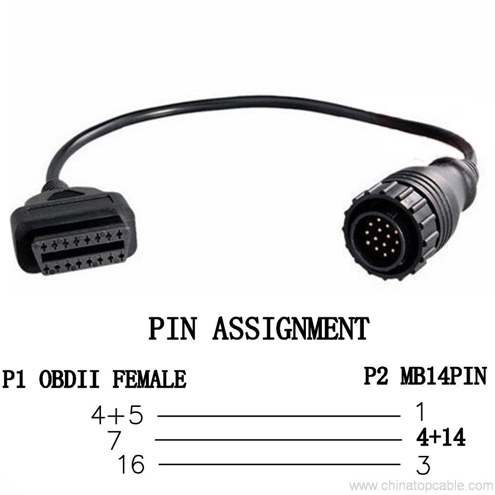
Nissian 14 PIN – 16PIN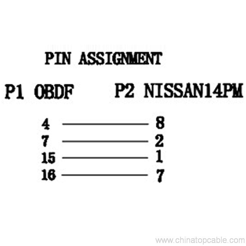
GM12 PIN-16PIN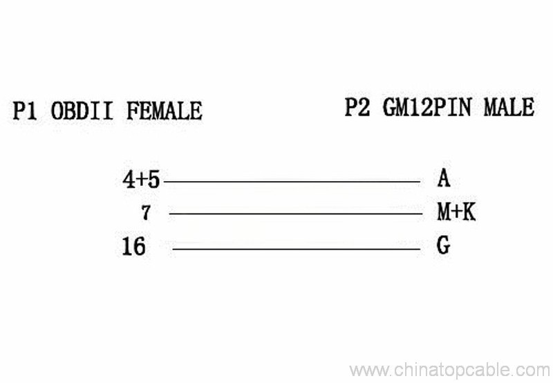
DB9-16 PIN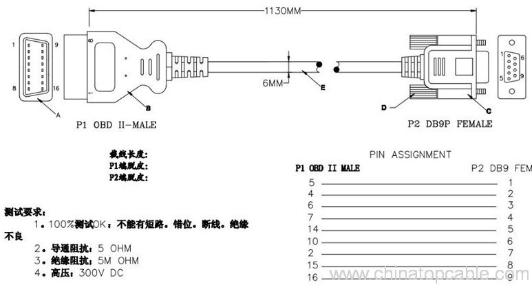
iveco 38pin -16 PIN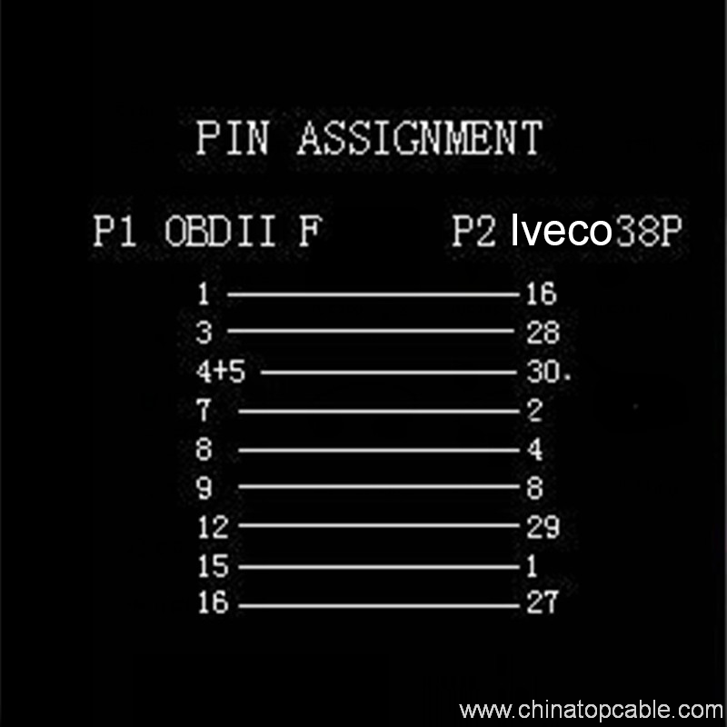
Fiat 3 PIN – 16 PIN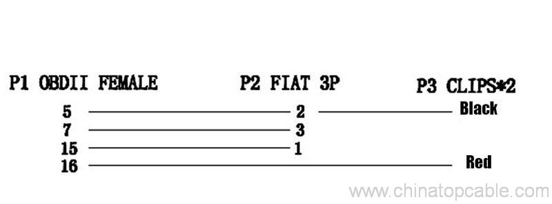
Toyato 22pin – 16 PIN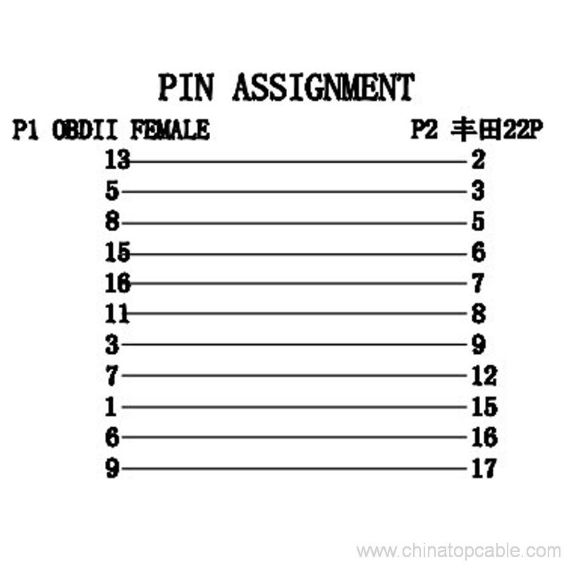
KIA 20 PIN – 16 PIN
Audi 2×2 – 16 PIN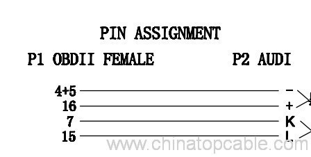
Benz 38 PIN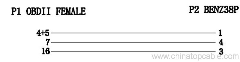
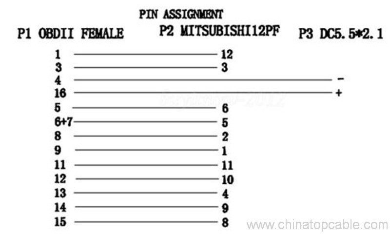
Mitsubishi 12 PIN – 16PIN
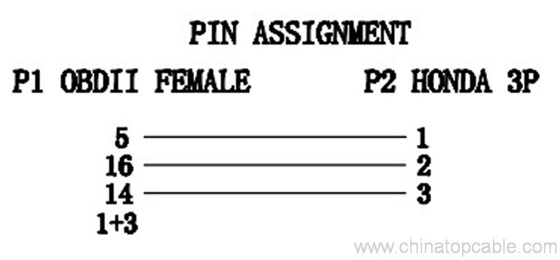
Honda 3pin – 16PIN
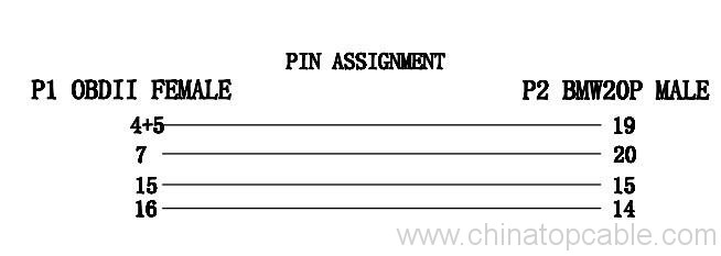
BMW 20 PIN – 3 PIN
Subaru 9 PIN – 16 PIN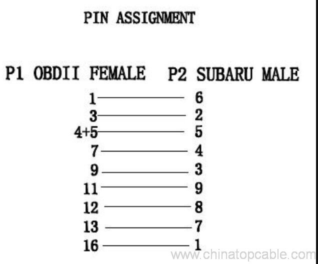
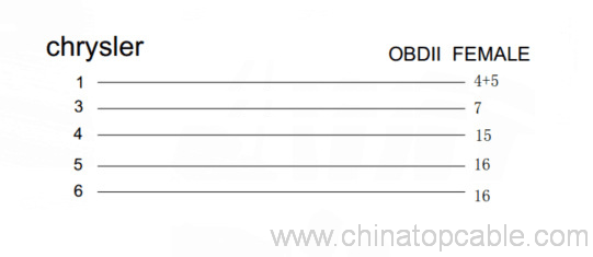
Chrysler 6 PIN