

A generic ELM327 dongle reaches one kind of vehicle: the one that already has the standard 16-pin OBD2 port under the dash. Point it at a KIA with a 20-pin socket, a Honda with a 17-pin socket, or a truck with a 9-pin round connector, and the app reports no communication on a vehicle that starts and runs perfectly. The answer is usually not a different dongle. It is a short passive cable that moves the right contacts onto the 16-pin positions the dongle expects. The two parts do separate jobs, and knowing which job belongs to which part saves a workshop a drawer full of trial and error.
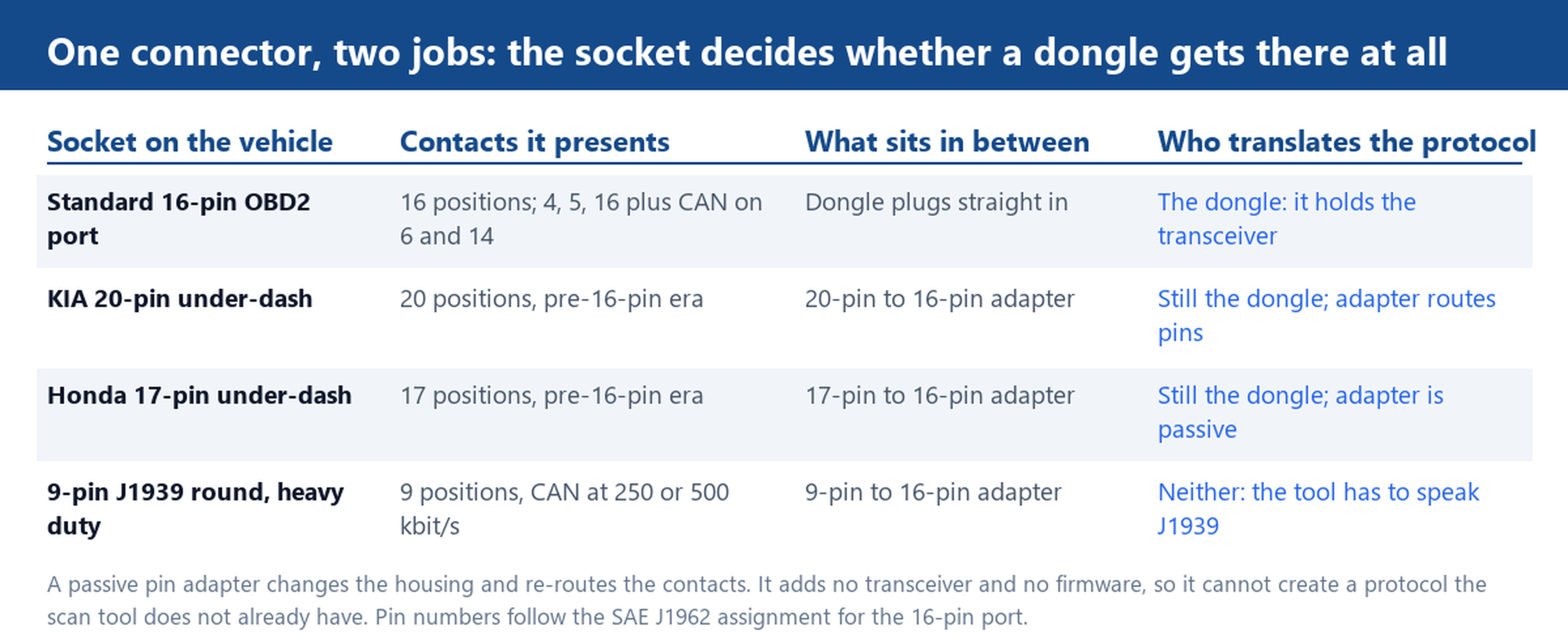
Two jobs in one connector: who translates the protocol, and who moves the pins
The dongle is the part with silicon in it. An ELM327 board carries a microcontroller and a CAN transceiver, and the firmware decides which protocols it can speak: ISO 15765-4 on CAN, and on most boards the older ISO 9141-2, KWP2000 and J1850 variants as well. That firmware is what turns voltage changes on two wires into a readable parameter such as coolant temperature or a stored trouble code.
A pin adapter has none of that. There is no chip inside, no driver to install and no firmware to update. It is a housing on each end and a set of contacts joined by wire in between, and its whole job is to stand between a socket the tool does not fit and a tool that knows the 16-pin layout.
That difference predicts the failure you will actually see. If the dongle lights up but the app reports no protocol, the contacts arrived and the protocol did not match, which is a tool problem that no adapter can fix. If the dongle stays dark, no supply reached it, which points at the pin map or at the vehicle feed. Two symptoms, two different purchase decisions, and a parts order that answers the right one.
When a 16-pin dongle is enough: pins 4, 5, 16 and the CAN pair on 6 and 14
The 16-pin port is defined by SAE J1962, and a handful of contacts carry the everyday work. Pin 4 is chassis ground, pin 5 is signal ground and pin 16 is battery positive at a nominal 12 V. Pins 6 and 14 are the CAN pair, high and low. On any car new enough to run diagnostics over CAN, those contacts are the entire conversation, and a dongle with nothing in front of it will read live data, freeze frames and stored codes on its own.
A two-minute check is worth more than a software reinstall. With the key in the position that powers the accessory circuits, measure between pin 16 and pin 4: you should see battery voltage. Across pins 6 and 14 an idle but live bus sits near 2.5 V on both lines and swings about a volt either side of that as frames go out. If pin 16 reads zero, look at the fuse feeding the diagnostic socket, which on many cars is shared with the cigarette lighter circuit.
CAN has been the required OBD2 bus in the US market from the 2008 model year, so a modern car is the easy case. The OBD2 cable range covers the straight-through and splitter builds that sit behind that port, and the pinout and code reference on this site lists the standard modes and parameter numbers. The hard cases are older vehicles, which is the next section.
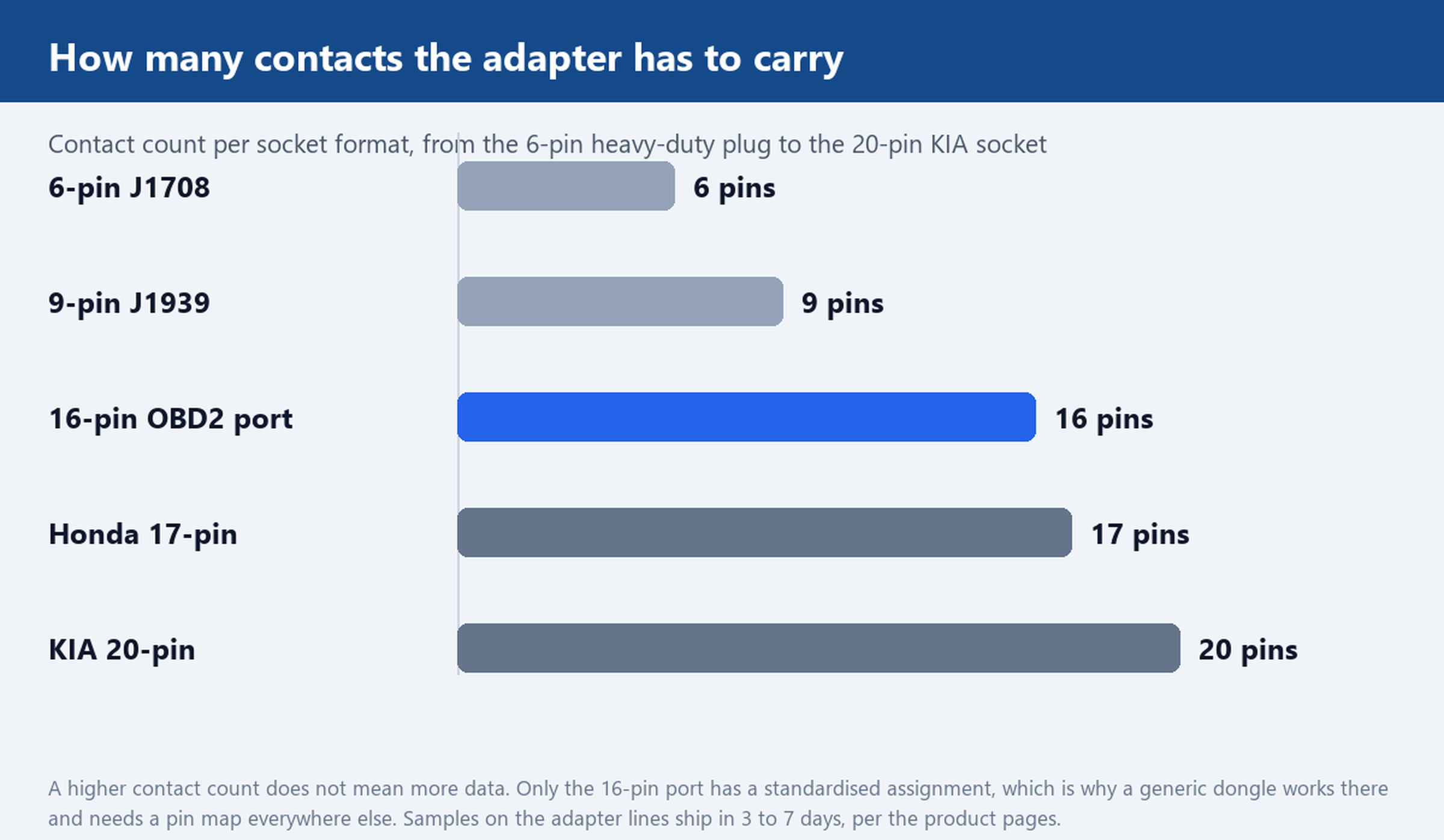
When you need a pin adapter instead: 20-pin KIA, 17-pin Honda and 37-pin truck sockets
Older sockets are where the adapter earns its place. The KIA 20-pin under-dash connector and the Honda 17-pin connector both predate the standardised 16-pin port, roughly the mid-1990s and earlier depending on market. Neither maps onto the 16-pin layout, so a 20-pin to 16-pin or 17-pin to 16-pin adapter goes in front of the same dongle and the same phone app.
Two scope notes matter here. First, a passive adapter routes the contacts that the older interface shares with OBD2, and it does not add protocols; which systems a scan tool actually reads still depends on the vehicle and on the tool software. Second, check the housing shape against a photograph before ordering, because the KIA 20-pin adapter and the Honda 17-pin adapter look similar on a parts list and are not interchangeable.
Heavy duty is a separate family again. A 9-pin J1939 round connector carries CAN at 250 or 500 kbit/s, and a 6-pin J1708 plug carries an older serial bus. A 9-pin to 16-pin adapter makes the physical connection, but the tool still has to speak the protocol on those wires, and a car-oriented dongle usually does not. Some European trucks use a 37-pin round connector; formats outside the stocked range are quoted as a custom pinout build against the drawing the buyer supplies, with the pin assignment written down before anything is cut.
Reading the limits: pin 16 voltage, K-line cars and adapters that power nothing
Three limits come up on a bench far more often than a failed cable.
The first is the pin 16 feed. Some sockets are live only with the ignition on, so a dongle that works on one vehicle looks dead on the next. Test with the key in the accessory position before opening a housing, and note what the vehicle needs, because the same technician will meet it again on the next car of that model.
The second is K-line. Cars built around ISO 9141-2 talk on pin 7, with pin 15 as the slower wake-up line. Many ELM327 boards support that pair, but a CAN-only board ignores it completely, and again no adapter changes that. If a workshop keeps one dongle for older cars, the protocol list on the board matters more than the connector on the end.
The third is the adapter that powers nothing. A build wired for data contacts only leaves pin 16 unconnected, so the scanner gets no supply and stays dark. If the adapter is meant to feed the tool, ask for the pin 16 and pin 4 wires to be part of the build and confirm continuity with a meter on arrival. The technical resource pages on this site carry the end-open assignments for exactly that check, pin by pin, so the test happens before the vehicle does.
Ordering both lines: what to specify on a pin adapter cable
What goes into the order is a short list, and every line prevents a specific return.
- Socket format and contact count, matched against a photo of the vehicle connector rather than a model year, since model years overlap on the change-over models.
- Tool-side connector: 16-pin male or female, because a plug-in dongle and a bench harness take opposite sexes.
- A pin-to-pin map as a written sheet, so the workshop can buzz out each contact before the cable goes into service.
- Overall length and the reach it has to make under the dash, plus whether the cable stays connected while the vehicle is driven.
- Jacket and temperature range: the Honda 17-pin line on this site is rated from minus 30 to plus 80 degrees Celsius, which is the cold-morning test that cracks a cheap jacket.
- Moulded strain relief and RoHS materials, the two items a purchasing sheet tends to drop and a workshop always notices.
Samples on the adapter lines ship in 3 to 7 days, which is long enough to check a pin map against a real vehicle and short enough to keep a production date intact. Ask for the sample with the pin sheet attached, run a continuity check on every contact, and only then commit the volume run.
Tell us the socket you are working with and the scanner you already own. We will confirm which pin adapter sits between them, send the pin assignment for approval, and quote samples of that exact build.