

OBD2 cables fail differently from pure signal cables, and that difference decides the test plan. A USB or HDMI cable only has to pass data; an OBD2 cable also carries the 12 V feed that powers the scanner, so a cable can pass every continuity check and still brown out a tool the moment it starts polling. If you know how to test OBD2 cable stock properly, you catch both failure modes at receiving time, before the cable reaches a mechanic who will blame the scanner or the vehicle. This is the bench procedure we recommend to repair chains and diagnostic tool sellers who buy in bulk.
What an OBD2 Cable Actually Carries: 16 Pins, Ground Returns and a 12 V Feed
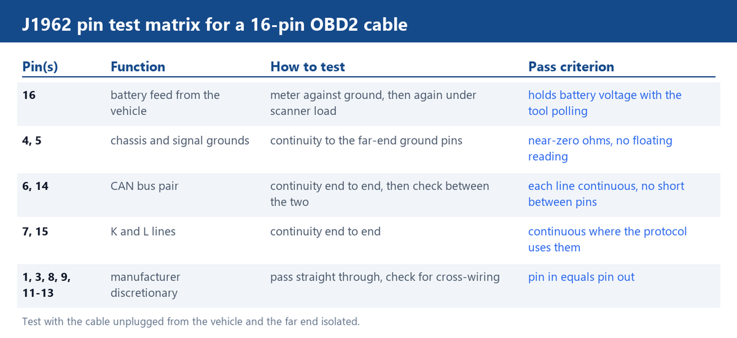
The J1962 connector allocates its sixteen pins into groups. Pin 16 is a battery feed taken from the vehicle, pins 4 and 5 are chassis and signal grounds, pins 6 and 14 form the CAN pair used by modern diagnostics, pins 7 and 15 carry the K and L lines, pins 2 and 10 carry the J1850 bus on some vehicles, and seven pins are left to manufacturer discretion. Our J1962 pinout reference lists the full assignment, and it is the sheet your QC bench should sit beside.
Two consequences follow for testing. First, continuity on the data pins alone proves nothing about the supply path, so the feed pins need their own checks. Second, because the scanner draws power from the vehicle through the cable, contact resistance that would never disturb a data line can drop real voltage on the feed. The tests below are ordered so the cheap checks come first and the load test last.
Continuity Test Pin by Pin with a Multimeter Before You Trust the Scanner
With the cable unplugged from any vehicle, put the meter in continuity mode and probe each pin at both ends against the map above. The pass rules are simple: every pin that should connect reads near zero ohms end to end, and no pin reads continuity to a pin it should not touch. The last check matters as much as the first. A solder bridge between the CAN pair, or between pin 16 and a discretionary pin, passes every individual continuity test and fails exactly when the scanner and the vehicle negotiate.
Work in a fixed order — feed, grounds, CAN pair, K and L lines, then the discretionary seven — and tick a paper map per unit. Bulk receiving goes fast once two people run opposite ends of the cable, and the map doubles as your defect evidence when a supplier conversation becomes necessary.
Checking the 12 V Feed and Ground Return Under Load, Not Open Circuit
Open-circuit voltage proves almost nothing on a feed line, because a corroded contact or a hair-thin trace reads full voltage with no current flowing. The honest test puts the circuit under load. Plug the cable into a vehicle or a bench supply, attach a scanner, and measure between pin 16 and ground at the tool end while the tool is actively polling. Then measure at the vehicle end. The difference is the drop across the cable, feed and grounds together.
Repeat the same measurement while the scanner runs its heaviest poll cycle, not while it idles at the menu. A cable that holds voltage at rest and sags under polling has a resistive joint that continuity missed, usually in a crimp. That unit goes back, because the fault will grow with every insert cycle of the plug.
Y Splitters and Extension Runs: Where Voltage Drop Shows Up First
A splitter such as the OBD2 1-to-3 Splitter, 16-Pin Male to 3 Female multiplies the current question rather than removing it. Every leg shares the same battery feed and the same ground returns, so the combined draw of a fixed logger plus a handheld tool is what the feed has to carry. Test a splitter the same way as an extension: load it with the devices you actually plan to run together, and measure the feed at the far end of each leg under simultaneous polling.
An OBD2 extension cable adds length, and length adds drop. If a vehicle plus extension plus splitter combination is your real deployment, test that exact stack on the bench rather than each part in isolation, because the resistances add in series and the margin you thought one part had belongs to the whole chain.
Pass and Fail Rules for Accepting a Bulk Lot
Write the acceptance rules down before the shipment arrives, and keep them mechanical enough that two inspectors reach the same verdict. Our recommended baseline: every pin continuous per the map, no shorts between adjacent pins, feed voltage at the tool end within a small fraction of a volt of the source under polling load, and plug insertion feeling firm with no wobble at the overmould. Any unit that fails one rule is a reject; a lot is accepted when the sample you pull passes all rules. Decide the sample size by your own incoming-inspection policy and apply it the same way every time.
The pay-off for a written procedure shows up in warranty months later: when a scanner misbehaves in the field, a logged acceptance test separates a cable fault from a tool fault in minutes. When you are ready to build the stock, order a sample OBD2 extension or Y splitter from our OBD2 cables or Y splitter categories and run this procedure on your own scanner before you place the bulk order. For harness-integrated builds, the open end pin assignment page extends the same map, and the custom cable page covers non-standard lengths and moulding.