

One balanced audio signal, two connector shells: the same hot, cold and shield conductors that end in a 3-pin XLR with a locking latch can also end in a 6.35 mm TRS plug held by spring contact. The XLR vs TRS cable decision is therefore not about which one sounds better on a healthy short run, because both carry the identical balanced signal. It is about which plug the equipment actually accepts, how the connection survives handling on a live stage, and how a mixed rack of consoles, amps and stage boxes stays consistent. This guide sets out where each connector belongs, how each one fails, and what to specify when you order cables for a rig that carries both.
One Balanced Signal, Two Shells: 3-Pin XLR and 6.35 mm TRS
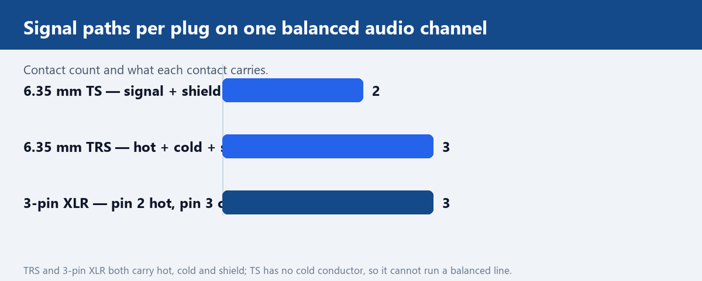
Both connectors carry the same three conductors for a balanced line. On a 3-pin XLR, the long-standing convention is pin 1 shield, pin 2 hot and pin 3 cold. On a 6.35 mm TRS plug, the tip carries hot, the ring carries cold and the sleeve carries shield. Electrically the two formats are interchangeable, which is exactly why an XLR to 6.35mm balanced cable works at all.
What differs is everything around those conductors. An XLR is a round shell with a latch that clips into the socket, and XLR microphone inputs also carry 48 V phantom power under the long-standing convention, so the connector family is built around powering and protecting the line. A TRS jack is a single rod-style plug: cheaper to tool, slimmer on a dense rear panel, and the format that audio interfaces and outboard gear default to when panel space is tight. Neither connector changes the audio on a short, undamaged run; what changes is the mechanical behaviour and the wiring discipline around it.
Locking Latch vs Spring Contact: Where Each One Fails on Stage
XLR fails in ways you can see. The latch either clicks in or it does not; a half-seated plug is visible at a glance, and a bent pin shows up in a normal cable check. Because the latch carries the pull-out load, a cable that gets stepped on or yanked usually pops the latch open instead of dragging the plug sideways out of the socket, and the fix is a re-seat rather than a hunt for the fault.
TRS fails in ways you hear first. The connection depends on the spring pressure of the socket contacts against the plug shaft, so the typical failure is gradual: crackles when the plug is nudged, a channel that drops when the rack shifts, or a plug that has worked partway out of a vertically mounted jack and still passes partial signal. On a standing install, seat every TRS plug fully and give each one a light tug during setup, then re-seat the ones on rear rack panels after any transport.
TS or TRS? Keeping Unbalanced Guitar Runs Separate
The third plug on stage is the 6.35 mm TS, with two contacts instead of three: tip for signal and sleeve for the shield return. An instrument output is unbalanced, so a guitar cable with TS plugs cannot be turned into a balanced run by changing the plug on one end. Plugging a TS cable into a balanced TRS input works electrically on many devices, but the source stays unbalanced, and the run keeps the noise behaviour of an unbalanced line.
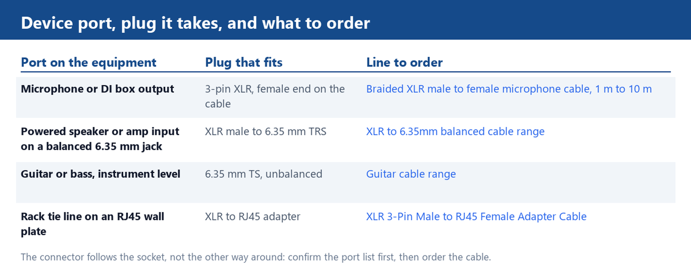
Keep instrument-level runs short, and when a guitar or bass has to reach the console across a stage, convert at the source with a DI box and continue on a balanced XLR run from the microphone and XLR cable range. That keeps the long leg balanced and leaves the TS plug to the short hop it handles well.
Patch Bay and Rack Wiring: Which End to Standardise
Mixed rigs get messy at the equipment end, not the cable end. A workable convention: run all long tie lines as XLR, and terminate to the gear with short adapters or patch leads where the device presents a 6.35 mm input. The latch-and-socket interface is the more reliable choice for anything that gets walked on, patched frequently or carries phantom power, so put XLR on the infrastructure and let the TRS plugs live at the device face.
Keep the gender convention consistent as well: the XLR female end faces the source output and the male end faces the input, which is how microphones and console inputs are wired. Label both ends of every tie line with the run number and the destination. If the rack mixes non-standard plate layouts, our cable customization service can build the adapter ends to match the panel you already have.
Order Spec: Lengths, Pack Sizes and Labelling for a Mixed Rig
Order by run, not by guess. Measure each stage run and each rack tie line separately; a braided XLR male to female microphone cable in our catalogue covers 1 m to 10 m, which handles mic drops, DI runs and console tie lines on one product line, and the same family is stocked in the PVC XLR cable range. For uniform patch stock, the same cable comes as a 2-pack and a 6-pack, so a touring case and a fixed install can draw from one shared spec.
Before the bulk order, close two gaps: confirm the port list of every console, amplifier and stage box, and confirm which runs are balanced and which stay at instrument level. The How to order page sets out the steps, including samples and packing. If you send us your console and stage box port list, we will ship one XLR female to 6.35 mm TRS balanced sample at the length you actually run, so you can confirm the fit on your own panel before the bulk order leaves the floor of our cable factory.