

Running a scan tool and a fleet GPS tracker from the same socket means choosing an obd2 y splitter cable for multi-module diagnostic setups that keeps every circuit intact. The vehicle gives you one 16-pin port, and both devices want power, ground and data at the same time. A well-wired splitter sends all of them to both branches; a cheap one quietly leaves pins out.
This guide covers the checks that separate the two before you commit to a bulk order.
Why Two Devices Want the Same 16-Pin Socket
Modern vehicles expose a single diagnostic connector under the dash, defined by the SAE J1962 layout. A workshop scan tool needs it during service, while a telematics or GPS unit is fitted permanently to report location and fault codes. Fleet operators often install the tracker first and then discover that the technician has nowhere to plug the scanner without unplugging it. Pulling the tracker to run a health check defeats the point of having it fitted.
The obvious fix is a Y cable with one male plug and two female sockets. The catch is that a connector having sixteen positions does not guarantee that sixteen circuits reach both ends. Some splitters wire the power and ground pins only to the second leg, on the assumption that an accessory just needs a supply. That works for a dash camera and fails the moment a scan tool tries to talk on the data bus. When both ends are live, the socket count looks identical from the outside, so the reliable way to tell is to trace what each branch actually carries.
Full 16-Pin Pass-Through vs Shared Pins
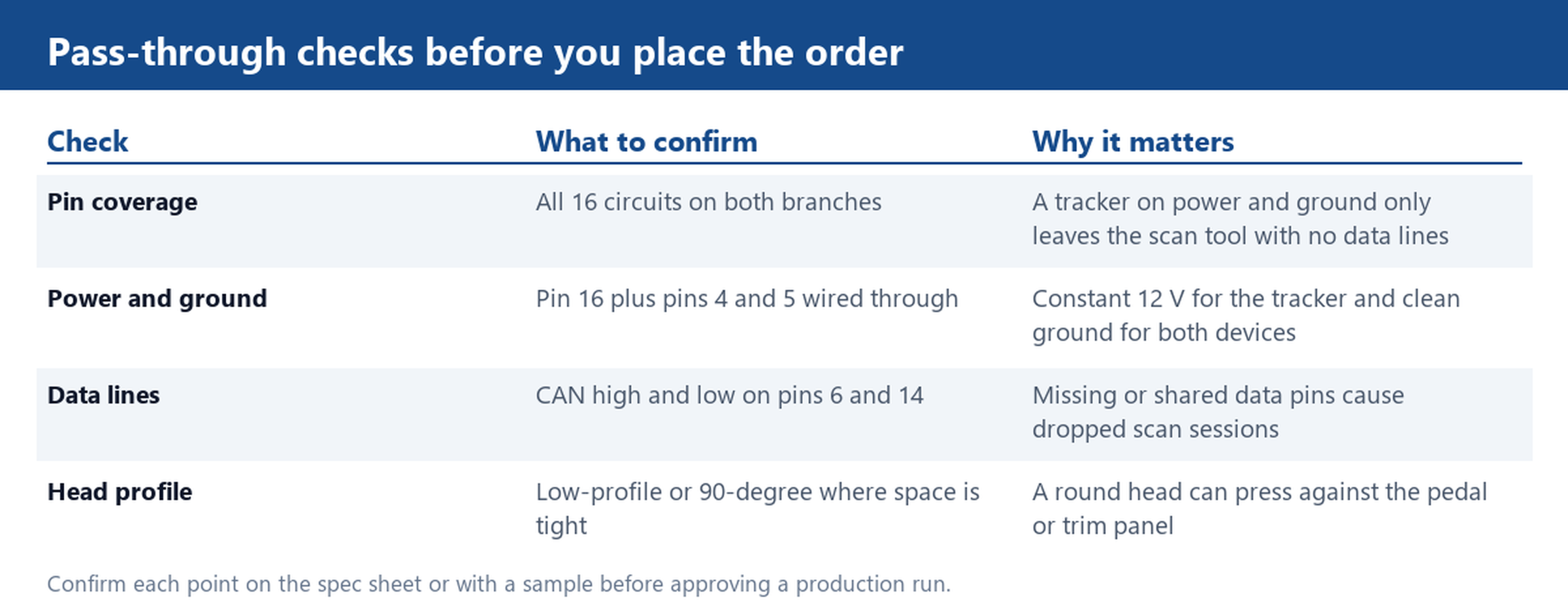
Ask for a full 16-pin pass-through build and confirm it on a sample. Pin 16 carries battery power, pins 4 and 5 provide chassis and signal ground, and the CAN pair sits on pins 6 and 14. A scanner contacts the ECU over those data lines; a tracker that is pinned only to power and ground cannot replace that conversation. If the second branch omits the CAN pair or the K-line on pin 7, the tracker still lights up while the scan tool reports no communication, which reads like a vehicle fault rather than a cable fault.
The opposite failure is sharing rather than omission. Where both sockets are tied to the same pins with no isolation, two active devices can pull against each other on the bus, and a diagnostic session drops intermittently under load. A pass-through harness keeps each branch electrically complete instead of splitting one signal between two consumers. If your device pair includes a tracker that only listens, confirm that its presence does not load the lines the scanner depends on. A quick bench test with both ends connected while logging live data will show whether the session stays stable. Ask the supplier for a pin-to-pin continuity map rather than a marketing description, and keep it on file for the next production lot.
Flat Noodle vs Round Head: Routing Under the Dash
Electrical correctness is only half the job. The connector lives above the pedal box, where a bulky moulding can press against the accelerator or the trim panel. A low-profile 90-degree head turns the plug sideways and clears space that a straight round shell occupies. Flat noodle and flat ribbon constructions spread the wires into a thin tape that slips under carpet edges and behind kick panels, while a round jacket of the same length is much harder to hide.
Before choosing, look at where each device will sit. A tracker mounted near the fuse box may only need a short tail, whereas a scanner plug that a technician reaches for every service is better kept accessible. Route the cable away from the steering column and moving pedals, and leave enough slack that the connector is not under tension. If the install is tight, a right-angle female head on the branch facing the bulkhead can turn an awkward fit into a clean one. Confirm the head orientation on a physical sample, since a drawing rarely shows how much room the boot needs once the plug is seated.
15 cm, 30 cm or 60 cm: Choosing Branch Length
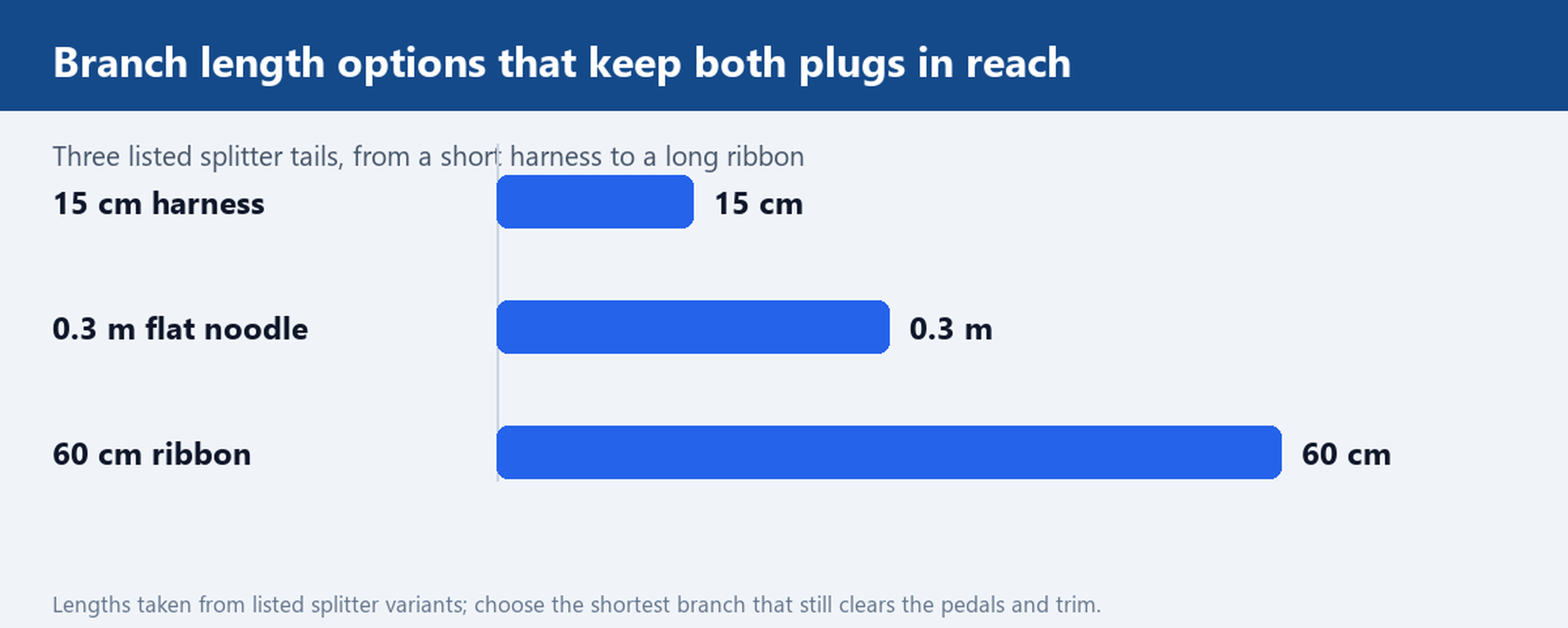
Branch length sounds like a minor detail until both plugs have to reach their devices at once. A 15 cm harness suits two units mounted side by side close to the port and keeps the wiring almost invisible. A 0.3 m flat cable gives enough room to tuck one branch behind a panel while the other stays handy for the technician. A 60 cm ribbon lets the tracker live further away, for example behind the glove box, without stretching the connection.
Pick a branch short enough to keep both ends clear of the pedals and trim, while still reaching each device. Extra cable that is coiled and zip-tied adds bulk and can rattle, and too much slack near a moving part is worse than a neat run. Where the two devices face opposite directions, a Y split with unequal branches is often easier to dress than two equal legs. Lengths should be checked against the listed variant rather than assumed from the product photo, because the same shell is sold with several tails.
Temperature Range and Materials to Confirm Before Ordering
A cabin is a harsh place for a cable. Parts of the dash can sit in strong sun for hours and then face a cold start, so the jacket and insulation must hold up across that swing without going brittle or soft. Ask for the stated operating range and the jacket material on the spec sheet, and confirm that the moulded strain reliefs stay firm at the upper end. A connector that feels solid at room temperature can loosen after repeated heat cycles, which shows up later as an intermittent fault that is hard to trace.
Finally, treat the first article as a test, not a formality: power both devices, log a live scan session, and check continuity on every pin before approving the run. Send us your port layout and device pair, and we will quote a 16-pin pass-through splitter with a sample.