

An XLR-to-RCA cable that passes signal can still be the reason a room sounds thin on one side or hums at the mains frequency. On a 1.5 m unbalanced run the meter answers faster than the ear, because the failures that matter here are resistive and structural: a cold joint on pin 2, a shield crimped onto the jacket instead of the braid, or a pin 3 landed on the second RCA tip so that the pair carries the same programme twice with one copy inverted. The four measurements below separate a good assembly from a bad one, and each comes with a number you can write into a receiving inspection sheet.
What an XLR-to-Dual-RCA Run Carries and What It Drops
A three-pin XLR carries one balanced channel. Pin 1 is the shield and the signal return, pin 2 is the hot leg and pin 3 is the cold leg, driven in opposite polarity so that the receiving stage can subtract one from the other and reject whatever noise both legs picked up on the way. An RCA jack carries one unbalanced channel: a single centre conductor inside a shell that doubles as the return.
Turning three wires into two means throwing one leg away and referencing what remains to the shield. That costs about 6 dB of level against the balanced connection, because the input no longer sums two anti-phase legs. The loss is expected and harmless. What is not harmless is a second RCA plug wired to pin 3 as though the cold leg were an independent channel. Feed that pair into a left and a right input and you have the same programme twice, one copy inverted; sum the two anywhere downstream, in a console matrix or a ceiling-speaker zone, and the signal cancels. Kept separate, the stereo image collapses to a point in the middle.
So the first thing to settle is which cable you are holding. On a stereo source, two XLR plugs are needed for two channels. A single XLR feeding two RCA plugs is a distribution cable, and in that case both tips belong on pin 2 with pin 1 as the shared return. The expected meter readings differ between the two types, which is why the test sheet asks for the type first.
Pin-to-Pin and Pin-to-Shell Continuity on a 1.5 m Assembly
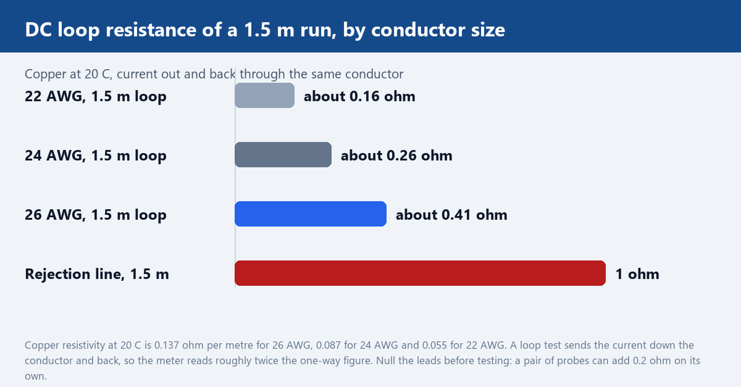
Disconnect everything, set the meter to its lowest resistance range and null the leads against each other. On a 1.5 m assembly the readings sit in a narrow band: roughly 0.4 ohm for 26 AWG conductors, 0.26 ohm for 24 AWG and 0.16 ohm for 22 AWG, because copper runs at 0.137, 0.087 and 0.055 ohm per metre at 20 C and a loop test passes the current through the conductor twice. Anything above 1 ohm on a run this short is a joint problem, not a wire problem.
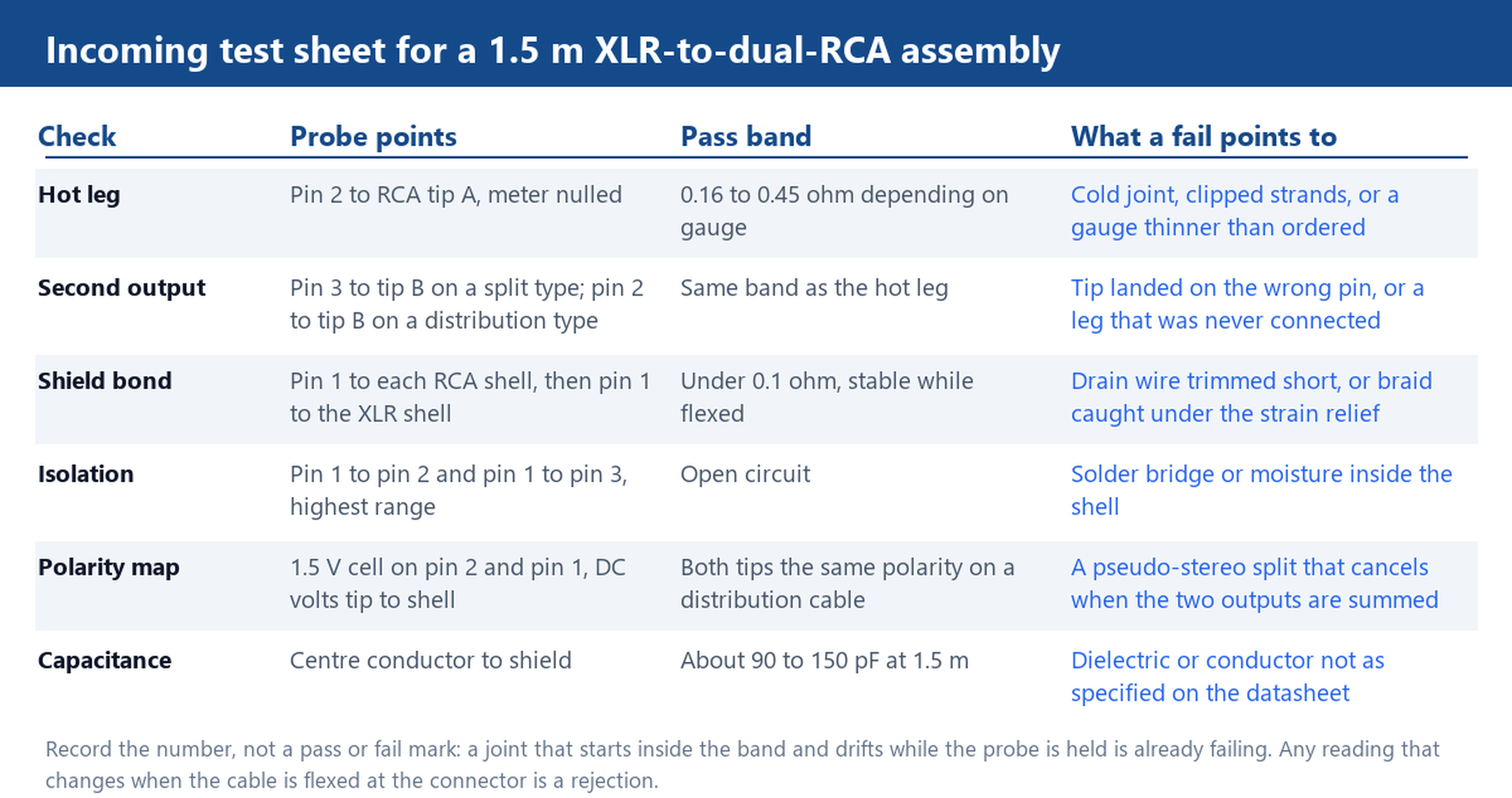
Probe in a fixed order so the readings can be compared across units. Pin 2 to RCA tip A. Pin 2 to tip B on a distribution cable, or pin 3 to tip B on a split cable. Pin 1 to each RCA shell in turn. Then pin 1 to the metal body of the XLR connector, which is the shell and not the pin. Finish with pin 2 to pin 3 and pin 1 to pin 2, both of which must read open circuit on the highest range.
Two behaviours matter more than the absolute value. A reading that starts inside the band and climbs while the probe is held is a crimp that has cut most of the strands; it will drift further under vibration. A reading that jumps when the cable is flexed at the connector is a joint that has already failed once and will fail again in service. Reject both, even when the number looks acceptable at the moment of the test.
Catching a Channel Swap Before It Reaches the Console
Channel swap in this family rarely means left and right are reversed at the plug. It means a leg has been landed on the wrong tip, so the second output carries an inverted copy of the first or carries nothing at all. Listening does not expose it reliably: programme with strong centre content sounds normal on either output alone and only collapses when the two are summed.
The definitive check needs no audio. Connect a 1.5 V cell with the positive terminal on pin 2 and the negative on pin 1, then measure DC volts from each RCA tip to its shell. A tip wired to pin 2 reads about +1.5 V. A tip wired to pin 3 reads about -1.5 V, because the cell is being read through the cold leg in reverse. A tip with no connection reads zero.
Two tips at the same polarity mean a distribution cable, which is correct for feeding two zones from one output. Two tips at opposite polarity mean the cable was built as a pseudo-stereo split, and that is a rejection whenever the purchase order asked for a distribution type. Write the polarity pattern next to the part number on the inspection record. A lot that passes continuity but maps the legs the wrong way is still the wrong lot, and the fault will surface as a complaint about a hollow-sounding room rather than as a dead channel, which is far harder to trace later.
Hum, Buzz and Shield Resistance: Testing the Return Path
On an unbalanced run the shield is the return conductor, so mains hum enters through it. An assembly bonded at the XLR end and floating at the RCA end still passes signal and still sounds acceptable on a bench. Install it in a rack with an earthed amplifier and the loop closes through the mains earth instead: the shield stops being a return and starts being an antenna, and the run picks up buzz that changes when a dimmer is switched.
Measure pin 1 to shell at both ends with the same nulled meter. Each end should read under 0.1 ohm. Half an ohm or more points to a drain wire trimmed too short, or a braid that was captured by the strain relief instead of being soldered to the shell. Flex the cable while watching the display; a shield reading that moves by an ohm or more under movement will produce intermittent buzz on site.
Two more checks belong on the sheet for any lot that is going into an installation rather than a demo room. Insulation between pin 2 and pin 1, measured on the highest range, must be open: a finite reading means a solder bridge or moisture inside the shell. Capacitance from centre to shield on a 1.5 m run typically lands between 90 and 150 pF, and a figure far outside that band suggests the dielectric or the conductor is not what the datasheet promised, whatever the jacket printing says.
One diagnosis is worth stating plainly, because it saves purchase orders. If the installation hums with the cable connected and goes quiet when the shield is lifted at one end, the assembly is fine and the building has a ground loop. Replacing cable after cable will not fix it. The remedy is a single bonded earth reference or a transformer-isolated interface between the two pieces of equipment.
A Pass and Fail Sheet for a Returned Lot
A returned lot has to be judged per unit, not per shipment, because every failure above is a joint-level defect that appears in a minority of pieces while the rest of the carton is sound. Test each returned unit, record the six readings, and decide rework or scrap from the record. The pass bands on the sheet come from the resistance of the copper in the run and from the behaviour of the shield bond, not from a supplier statement, which makes them defensible when a credit is being argued.
The same sheet works as an incoming check on a new lot, with one change: sample the first and last unit of each carton rather than every piece, then open a full inspection only if a sample fails. The two measurements that catch the most defects per minute spent are the shield bond at both ends and the polarity map, because a continuous but wrongly wired cable passes every listening test a warehouse can run.
For assemblies that need a different length, a different connector shell or a specific leg mapping, the custom cable service builds to drawing, and the factory page describes how production and inspection are run. The XLR to RCA range and the wider microphone and XLR cable catalogue are the places to shortlist from, and the audio and video cable section covers the rest of the analogue runs in the same rack.
Send the failing run together with the connector layout and the readings you took, and we will test a 1.5 m XLR-to-dual-RCA sample against the same pin and shield checks before you re-quote the lot.