

A Micro USB cable order rarely fails on exotic technology. It fails on three decisions made before the first sample ships: the plug has to match the socket in the device, the current label has to be backed by conductor gauge and length, and the build has to be either charge-only or charge-and-sync, with nothing left to guess. Vehicle accessories, security keypads, small appliances and retail counter stock still consume Micro-USB fittings in large batches, and a wrong pick on any of those three points sends a whole lot back for rework. This Micro USB cable buying guide walks through each decision with the checks that catch the problem at sample stage instead of after the bulk lot lands.
Start with the plug: 5-pin Micro-B and the adapter question
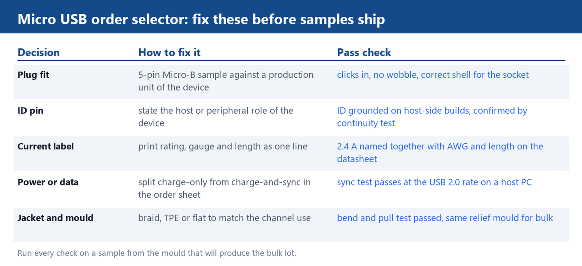
Micro-B is a five-pin plug. VBUS and GND carry power, D- and D+ carry the data pair, and the ID pin signals an on-the-go arrangement between a host and a peripheral. Because the shell is keyed, a correct plug clicks in with no wobble and cannot be inserted the wrong way round. That sounds trivial, and plug fit is still a frequent cause of returns in mixed-device channels: a plug built on a worn or out-of-date moulding tool will seat loosely in a socket that a correct sample seats firmly.
Mini-B shares the five-pin layout but the shell is taller and narrower, and the two plugs are not interchangeable. Adapter cables and Micro-B to Mini-B converters exist, and they make sense for service kits that have to open older hardware. For a volume accessory, though, an adapter in the box is a warning sign: it means the plug on the cable does not match the socket on the device the channel actually sells. Specify the plug that mates with the production unit and keep adapters as a separate line item.
Check the ID pin as well. If the device acts as a host, such as a diagnostics dongle or a card reader that reads a storage stick, the ID pin must be tied to ground inside the plug. A charge-and-sync build with a floating ID pin will power the peripheral and then fail to enumerate it. Ask for pin continuity on one sample from each moulding batch and the question closes in five minutes with a multimeter.
Why two cables labelled 2.4A can behave differently
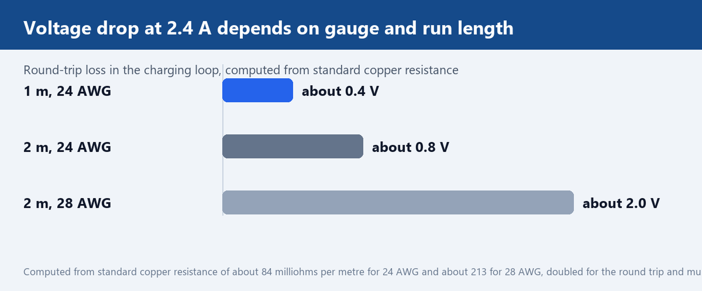
The 2.4A print is a capability claim about the whole assembly, and the assembly is copper plus length. Standard copper resistance values put 24 AWG at roughly 84 milliohms per metre and 28 AWG at roughly 213 milliohms per metre, and the charging loop runs through two conductors, so the round trip doubles those numbers. Multiply by 2.4 A and the arithmetic becomes concrete:
- 1 m at 24 AWG: about 0.17 ohms round trip, so roughly 0.4 V lost at 2.4 A.
- 2 m at 24 AWG: about 0.34 ohms round trip, so roughly 0.8 V lost at 2.4 A.
- 2 m at 28 AWG: about 0.85 ohms round trip, so roughly 2.0 V lost at 2.4 A.
A 5 V bus that loses 2 V in the cable leaves the device very little to work with, and the charge circuit simply throttles back. This is also why the 2.1A label exists next to the 2.4A label: it is frequently the honest rating for a longer or thinner build, where the factory has derated the print to match the copper. Two cables on a shelf can both say 2.4A and still deliver different charge rates from the same charger.
Close the gap at sample stage with one line on the datasheet: current rating, gauge and length printed together, for example 2.4 A at 24 AWG for 1 m. Then verify with a USB meter and a load that draws the rated current, and read the voltage at the device end rather than at the charger end. If the drop is bigger than the datasheet implies, the copper inside is not what the print claims.
Charge-only or charge-and-sync: the data pair decision
A charge-only build carries two power conductors and skips the data pair, which saves cost and keeps the assembly thin. It is the right choice for wall adapters, powerbanks and retail counter chargers where the device never talks back. A charge-and-sync build carries the full five-pin layout and moves data at the USB 2.0 rate of 480 Mbps, which any device with a configuration menu, a firmware update or a companion app needs.
The failure mode is quiet: a charge-only cable in a sync application powers the screen normally and then shows the device as not recognised, and support tickets follow. Split the requirement in the order sheet instead of in the warehouse. Our charger cables cover the power-only builds, while the USB 2.0 cable range covers assemblies with the full data pair, and a bulk order can mix both if the channel sells two device families.
Jacket and strain relief: braided, TPE and flat builds
Length and jacket shape should follow where the cable lives. Short builds around 13.5 cm suit keychain and powerbank carry; 1 m covers the desk and the retail counter; 2 to 3 m reaches dash cams, security keypads and bedside sockets. The Micro USB cable catalogue carries all three families, and the difference shows up in how the channel packages them.
Jacket material is a service-life decision more than a cosmetic one. Nylon braid resists abrasion where the cable gets pulled across a counter or coiled into a bag daily. TPE stays flexible in cold weather, which matters for vehicle accessories left in a car overnight. Flat and zipper builds tangle less in accessory bundles and lie flat under a device. Spring and zinc-alloy builds absorb the plug-pull at checkout counters, and a 90-degree elbow keeps the plug from snapping in a car mount.
Whatever the jacket, the part that fails first is usually the joint between the plug and the cable, so the strain relief mould deserves as much attention as the print. Bend the sample through the radius it will see in real use and pull-test the plug. If the relief is right, the conductor fatigues nowhere near the joint. Our factory runs the same mould for sample and bulk so the relief you approved is the relief that ships, and the customize cable page covers jacket colour, length and logo printing for channel branding.
What goes on the spec sheet and the sample request
Five lines cover a Micro USB order properly. First, the plug: 5-pin Micro-B, with the ID pin requirement stated if the device hosts a peripheral. Second, the electrical claim: current rating together with gauge and length, such as 2.4 A at 24 AWG for 1 m. Third, the function split: charge-only or charge-and-sync at the USB 2.0 rate. Fourth, the jacket and mould: braid, TPE or flat, with the strain relief named. Fifth, packaging: retail card, polybag or bulk box, since accessory channels ship on the card as much as on the cable.
Send the device model, the current it draws and the length your channel sells, and we will ship a 1 m 2.4 A and a 2 m 2.1 A sample with the same moulded strain relief so you can test both before the bulk order. The how to order page walks through the sample and quotation steps, and the same contact handles both.