

A debug cable is the cheapest part of an embedded build and the one that can burn out the most expensive part of the board. When a USB TTL cable for embedded development is chosen badly, the cause is almost never cable length or transfer speed. It is a logic level mismatch between the adapter and the microcontroller, or a plug shape that does not match the debug jack on the board. Get those two right and the cable disappears from your list of problems; get either one wrong and the UART can be damaged on the first connection. Here is how we walk buyers through the choice.
What a USB to TTL Cable Does on a Development Board UART Header
The cable contains a USB-to-serial bridge chip and a small amount of supporting logic. On one end is a USB plug your PC treats as a virtual COM port; on the other end are the transmit, receive, voltage and ground leads that land on the UART header of the board. Everything the bridge chip sends comes out at the logic level of its own supply rail, not at some negotiated level, so the rail the cable carries is the rail your MCU pins will see. That is the whole reason the level marking on the cable carries more weight than any speed figure on the box.
The same rule applies to power leads. Many debug cables expose a VCC line taken from the 5 V USB rail through the bridge supply; whether that line reads 5 V or 3.3 V depends on the variant, and plugging it into a rail that expects the other level can back-feed the board. Treat the VCC lead with the same care as the data leads.
Logic Level First: 3.3 V Boards, 5 V Boards and What the Wrong One Does to the UART
Check the datasheet of the MCU before anything else. Modern boards overwhelmingly run 3.3 V logic, and many of those MCUs specify input pins that are not tolerant of 5 V. Driving a TX pin of that kind from a 5 V cable can latch up or degrade the input structure, and the failure sometimes shows up days later as an intermittent UART rather than an obvious burnout. A 3.3 V cable talking to a board that runs 5 V TTL usually fails in the opposite direction: the logic high of the cable sits below the level the receiver expects, and you get garbled console output instead of silence.
The practical check takes two minutes. Find the supply rail of the UART pins on your board, note whether the pins are listed as 5 V tolerant, then order the cable whose level matches. Our USB TTL cables come in both 3.3 V and switchable variants, such as the USB to TTL Serial Cable, 3.3 V, FT232RL and the USB to TTL Serial Cable, FTDI FT232RL, 3.3 V/5 V, so the level decision is a stock decision rather than a redesign.
The Chip Inside: FT232RL and Why It Decides Your Driver Situation
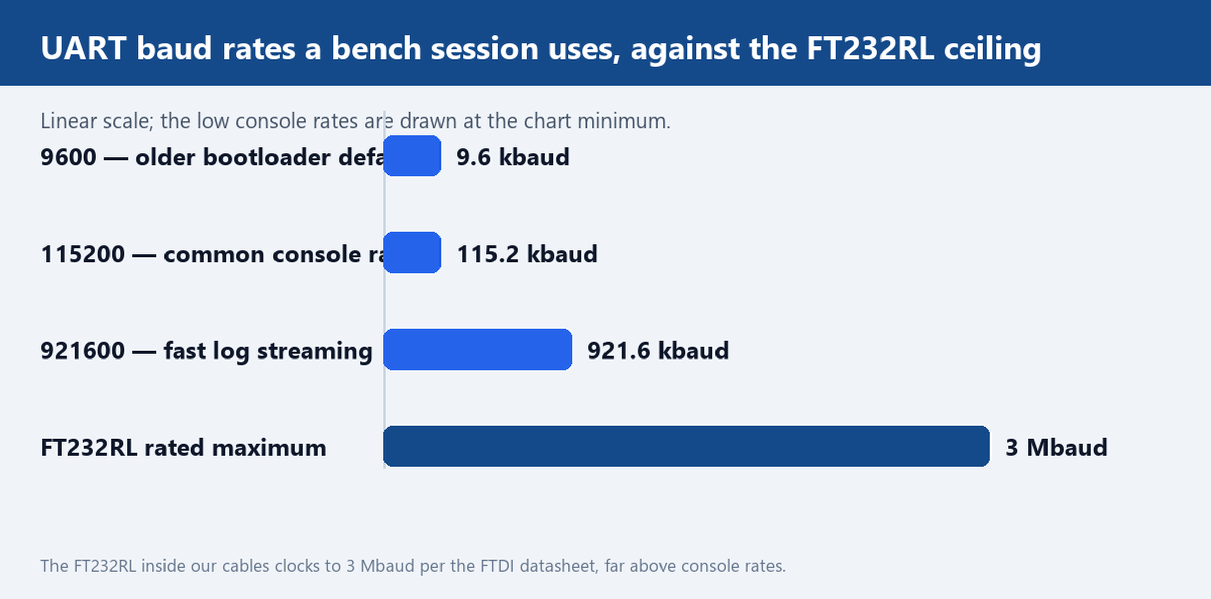
The bridge chip decides two things that matter in a pilot build: which driver the host needs and how fast the link can clock. The FT232RL is the most widely supported serial bridge in the embedded world; drivers are published for current Windows, macOS and Linux kernels, and our driver and software download page collects them so a new workstation needs no hunting. Its rated ceiling of 3 Mbaud sits far above anything a console session or a bootloader uses, as the chart above shows, so speed is never the reason to compromise on the level or the plug.
One more practical benefit matters to procurement teams: a single chip across the whole pilot batch means one driver image, one set of COM port behaviours and one configuration script. Mixed-chip batches look cheaper per unit and cost the day when half the workstations behave differently.
Connector Endings Compared: Bare Pins, 2.5 mm Jack and 3.5 mm Audio Jack
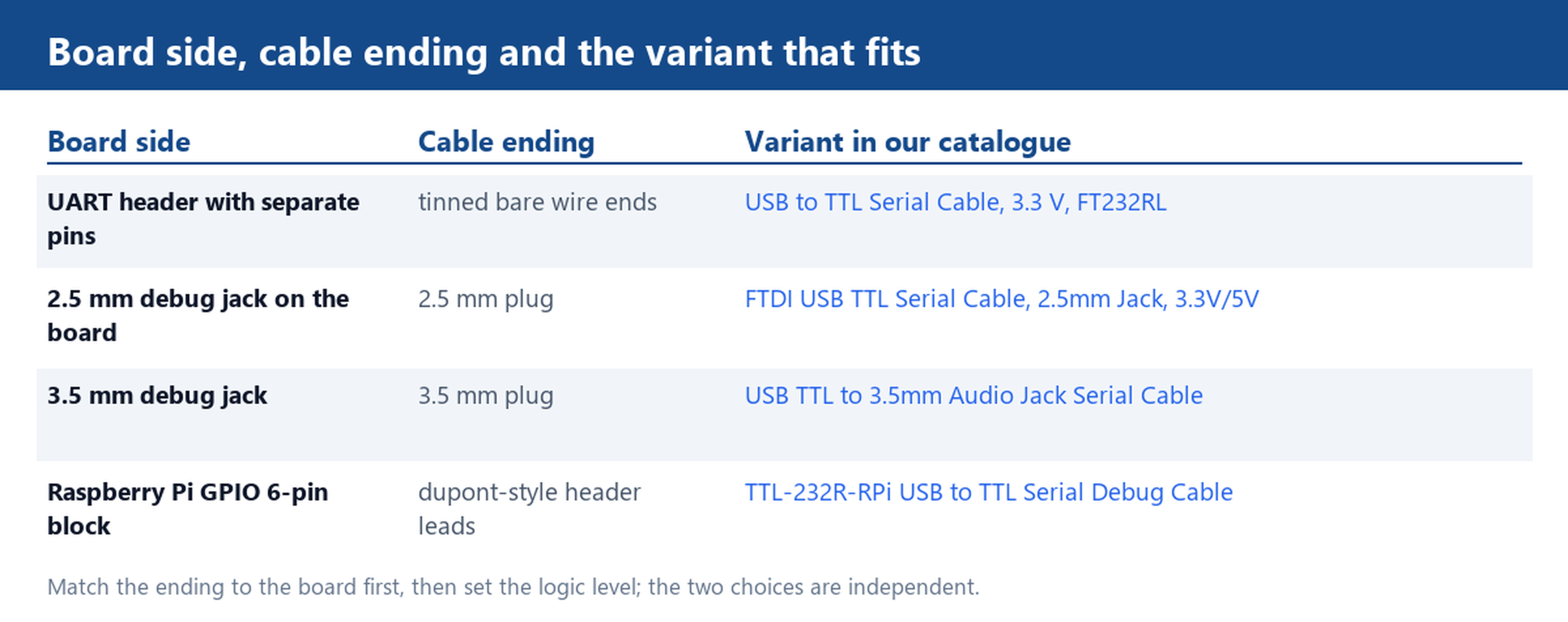
Boards expose their UART in three common ways, and each wants a different ending. A header with separate pins wants tinned bare wire leads you land individually. A growing number of dev boards route the UART to a 2.5 mm debug jack, which wants the FTDI USB TTL Serial Cable, 2.5mm Jack, 3.3V/5V. Boards that borrow the 3.5 mm audio jack form factor want the USB TTL to 3.5mm Audio Jack Serial Cable, and single-board computers such as the Raspberry Pi want the TTL-232R-RPi USB to TTL Serial Debug Cable, whose leads land on the 6-pin GPIO debug block in order.
The ending choice is mechanical, not electrical, which means you can settle it from a photo of the board. Measure the jack diameter or count the header pins, then match the variant. If the board is a custom design heading to production, this is also the point where a moulded ending of your own specification makes sense, and our factory tooling handles that as a normal order rather than a special favour.
Writing a Debug Cable Spec for a Pilot Build
Put three decisions on one line and the PO writes itself: logic level, bridge chip and ending. A line that reads 3.3 V, FT232RL, 3.5 mm plug, 1.8 m can be quoted, built and shipped without a single follow-up email; a line that reads USB debug cable, 50 pcs invites the supplier to guess the two parameters that can kill your board. For pilot builds we recommend keeping the level and ending identical across the batch even when boards differ, because the goal of a pilot is repeatable bench behaviour, not variety.
When you are ready to order, send your board logic level and a photo of the header; we will confirm the matching cable variant and ship a sample for your bench test. Start from the USB TTL cables category, or if your bench still runs legacy gear, our USB to DB9 RS232 cables cover the RS-232 side. Full ordering details live on the how to order page.