

A passive XLR Y split is the cheapest way to feed two destinations from one source, and it is also the part most often ordered by guessing from a photo. What comes back as a complaint is rarely silence. It is a leg that sits a fraction quieter, a hum that appears only when both destinations are plugged in, or a condenser microphone that behaves on one console channel and not on the other. Each of those traces back to the gender combination or to the way the three pins are carried on both legs, not to the copper inside the jacket. This guide works backwards from the two jacks in front of you, and finishes with the checks that belong on the sample before a bulk order.
How to Choose XLR Splitter Cable by the Jack, Not the Photo
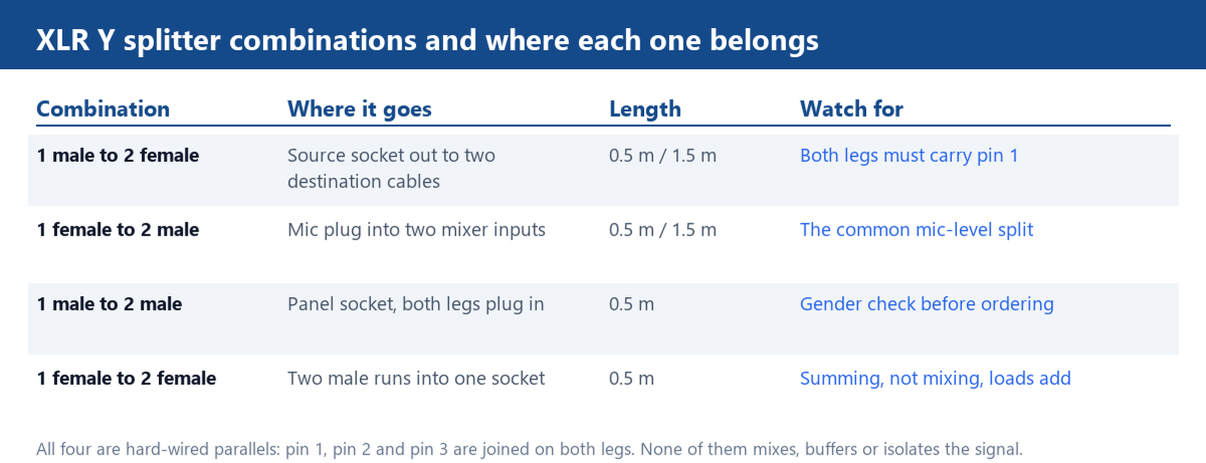
The XLR splitters in this range come in four hard-wired combinations that ship as separate part numbers, and once the plugs are loose in a bag the difference stops being obvious. The rule that settles it: count the connectors at both ends of the chain. The single end has to be the gender that mates with the connector on your source, and the two legs have to be the gender that mates with whatever your destinations present.
- 1 male to 2 female. The single male plug goes into a socket on the source side and the two female legs accept male-ended runs out to the destinations. This is the version used to record one source while feeding a second destination, and it is the one most often bought by mistake when the destinations are mixer channels.
- 1 female to 2 male. A microphone plug lands in the single female end, and the two male plugs go straight into mixer or interface inputs, which are female sockets. For mic-level work this is the combination that actually fits, which is why it is worth starting the search with the 1 female to 2 male 0.5 m patch splitter rather than with the more photographed version.
- 1 male to 2 male and 1 female to 2 female. Panel, wall-box and adapter work, where the socket you are standing at is the wrong gender for the run you already own. These are 0.5 m parts by nature.
Inside all four, the wiring is the same three-way parallel joint. Pin 1 joins pin 1, pin 2 joins pin 2, pin 3 joins pin 3, on both legs. If one leg has pin 1 connected and the other does not, the second destination has no shield return, and the symptom shows up much later as hum or as a channel that picks up a nearby dimmer. Ask for continuity on all three pins on both legs before you accept a sample. It takes a meter and two minutes, and it is the single check that separates a usable splitter from a return.
0.5 m at the Patch Point, 1.5 m From the Source
Length is decided by where the two destinations sit, not by what happens to be in stock. 0.5 m is the rack and patch-panel length: both legs stay inside the same bay, the joint sits behind the panel, and there is no spare loop to catch on a drawer. 1.5 m is for the case where one destination is on the same stand as the source and the other is a monitor send a stand away, which is what the 1 male to 2 female 1.5 m splitter is cut for.
Past roughly 1.5 m the passive form starts working against you. The two legs share one jacket and one moulded junction, so a tug on the longer leg loads the joint that both signals pass through. When the second destination is across a stage, run a plain XLR from a splitter box or use a second output instead of stretching a Y. The splitters in this range are built with moulded strain relief and a PVC jacket over pure OFC conductors, which is the right construction for rack work. It is not a substitute for tying the cable off where it leaves the bay, and a long Y is where that shows first.
Two Inputs in Parallel: What the Combined Load Does to Level
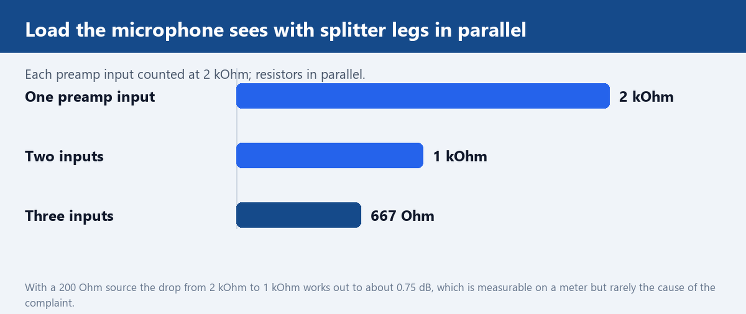
A passive split does not lower the signal, it lowers the impedance the source has to drive. Two preamp inputs of about 2 kOhm each, wired in parallel, present 1 kOhm; three present about 667 Ohm. A dynamic microphone with a 150 to 300 Ohm source impedance is designed to work into a load at least five times its own, so 1 kOhm is still inside the comfortable range.
Put the number where it can be checked. With a 200 Ohm source, dropping the load from 2 kOhm to 1 kOhm costs about 0.75 dB. That is the entire electrical penalty of adding the second leg, and it is not what buyers are hearing when they report one leg quieter. The usual cause is a destination mismatch: one leg into a microphone input and the other into a line input, which sit roughly 40 dB apart in sensitivity, or a leg with pin 3 floating so that input sees an unbalanced signal at 6 dB down.
Test it the same way every time. Measure the source open-circuit, then each leg terminated into its real destination. A pair of readings within a decibel of each other is a healthy split. A gap of several decibels is a wiring or destination problem, and no amount of cable swapping will close it.
Phantom Power on Both Legs: Safe for Two Mics, Risky Into a Line Input
Phantom power is 48 V applied in common mode to pins 2 and 3 through a resistor in each preamp, typically 6.8 kOhm per pin. Two preamps on the two legs each bring their own feed, so the microphone sees 48 V rather than 96 V, and the two feeds share the current draw instead of doubling it. Splitting a condenser microphone into two microphone inputs is normal practice and stresses nothing.
The risk sits at the other end of the chain. If one leg runs into a line input, an instrument input or an output, 48 V is now present where the circuit was never designed for it. Some line stages tolerate that, some do not, and the failure is not always immediate. Turn phantom off on the leg that does not need it, and if a destination cannot take 48 V at all, use a transformer-isolated split or a DC block rather than a passive Y.
Ground Loops on a Passive Split, and What to Check on the Sample
Both legs share pin 1 by construction, so both destinations are tied to the same shield. If they sit on different mains circuits, that shared shield is a loop, and the loop picks up hum at the mains frequency. The diagnostic is a sequence, not a guess: leg A alone, leg B alone, then both together. A splitter that is silent on each leg and hums on both is not faulty, it is doing what a passive split does, and the fix belongs in the grounding or in an isolated split.
The sample check that catches the rest:
- Continuity from pin 1 to pin 1, pin 2 to pin 2 and pin 3 to pin 3, on both legs.
- No short between pin 2 and pin 3, and no short between pin 1 and either signal pin.
- A pull test on each plug body with the cable held, not the connector.
- Both legs into two channels of one console, phantom off first, then phantom on the channel that needs it.
Custom lengths and packing run per order on this range, and samples ship in three to seven days, long enough to run those four checks before committing to a production quantity. The same split is also available hardwired into a stage box for permanent installs, which removes the shared-jacket joint from the argument entirely.
Tell us the source, the two destinations and the distance between them, and we will confirm the gender combination and length, then send a sample for a bench test. If the destination list already has mixed input types, say so in the first message and we will flag the leg that needs attention before the order is placed. The wider microphone and XLR cable range covers the single runs, patch cords and stage-box tails that go either side of a split.