

If you are sourcing a bnc cable for cctv cameras, the first decision is not length or connector finish. It is impedance. A 75 ohm coax carries the video signal cleanly over the distances a recorder expects, while a 50 ohm cable such as RG58 belongs to radio frequency and data links, not to the video run itself. Get that choice wrong and no amount of shield quality will recover the picture. This guide covers only three things that decide a cable: impedance, how jacket and diameter behave on a real install, and what the datasheet line and the termination actually tell you.
Which CCTV runs are 75 Ohm, and what a 50 Ohm RG58 cable is for
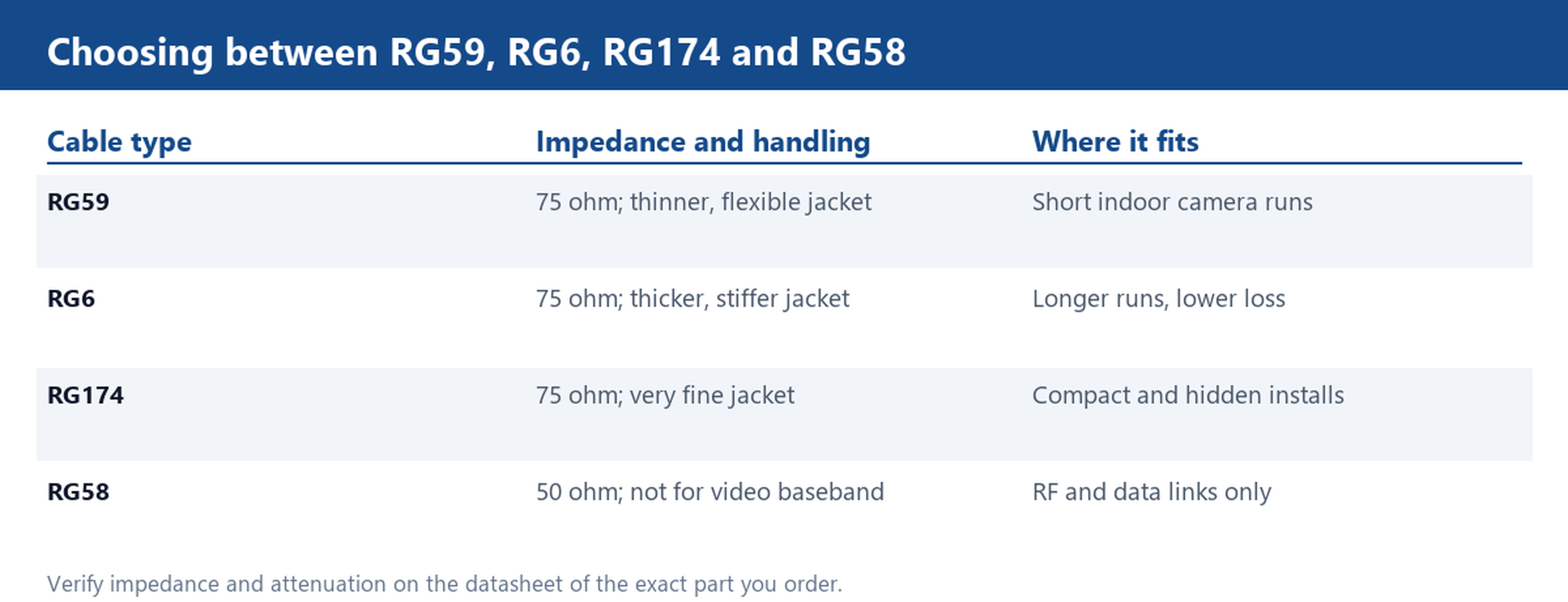
Analog and HD over coax camera systems are built around 75 ohm characteristic impedance. The camera output, the cable and the recorder input are all designed as a 75 ohm chain, and the BNC connectors used on that chain are the 75 ohm version. When the chain stays at 75 ohm, the signal reaches the recorder with the level and timing it expects.
RG58 is a 50 ohm cable. It uses the same BNC shell shape, which is exactly why it gets ordered by mistake for camera runs. The connector fits, but the impedance step at each end sends part of the signal back toward the camera. On a short bench lead the picture may still look fine; over a real run the result is ghosting, reduced contrast and edge ringing. Keep 50 ohm cable for RF and instrumentation, and reserve it for those jobs. Our CCTV and video BNC range lists RG6, RG58, RG59 and RG174 side by side so you can specify the impedance you actually need: CCTV & Video BNC Cable, RG6 RG58 RG59 RG174.
RG59 vs RG6 vs RG174: jacket stiffness, bend radius and loss per metre
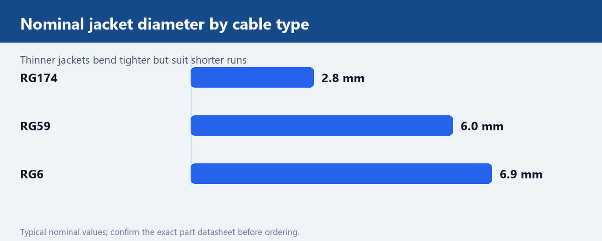
All three can be supplied as 75 ohm coax, so the choice comes down to handling and loss. RG59 has a smaller, softer jacket and bends easily around camera brackets and conduit turns. It is the usual pick for shorter indoor runs where flexibility matters more than long distance performance. RG6 has a larger, stiffer jacket and lower attenuation per metre, which is why it is preferred for longer cable paths and runs that pass near interference sources. The trade off is bend radius: force a tight bend into RG6 and you deform the dielectric, which changes impedance locally and creates the same reflection problem you were trying to avoid.
RG174 is much finer again. It suits compact housings, miniature cameras and hidden installs where there is simply no room for a full size jacket. The penalty is higher loss, so keep RG174 runs short. A practical rule is to respect the minimum bend radius printed on the cable rather than the tightest corner the installer can manage.
Reading the datasheet: attenuation, VSWR and mating cycles
A supplier datasheet line may read 0.24 dB at 6 GHz, VSWR 1.15 and 500 mating cycles. Those three figures answer three different questions, and it is worth knowing which is which before you compare quotes. Attenuation at a stated frequency tells you how much signal the cable loses; always compare it at the same frequency and for the same length, because a number without those two conditions is not comparable. VSWR describes how well the cable and connector match the system impedance. A value of 1.15 is close to the ideal of 1.0, meaning very little power is reflected; a value that climbs with frequency is a warning about the termination or the cable construction.
Mating cycles tell you how many connect and disconnect actions the BNC interface tolerates before the contact degrades. That matters on a patch panel or a camera that gets serviced, and matters less on a cable that is plugged in once and left. Ask for the datasheet of the exact part number you are ordering rather than accepting a family specification, and check that the figures are stated at a frequency and length relevant to your run. Where a standard part does not match your impedance, length or jacket requirement, a custom cable build is the route to a defined specification rather than adapting an off the shelf part.
Solder-cup or compression termination, and the centre pin that pulls out
How the BNC is attached is as important as the cable itself. A solder cup connector is attached with a soldering iron and suits low volumes, repairs and custom lengths. A compression connector is crimped with a dedicated tool and gives a more consistent mechanical and electrical result, which is why it is common on production runs. Whichever you choose, the centre conductor and the braid must both be captured correctly; a stray braid wire touching the centre pin will short the line.
The failure mode to ask about is the centre pin pulling out of the connector under strain. This usually happens when the cable jacket is not gripped and all the pull load lands on the pin and its solder joint. Look for a connector with a proper cable entry and strain relief, and specify it explicitly on the drawing. Our BNC coaxial brass compression connector cable, RG59 is an example of a compression terminated assembly. Also confirm connector gender and angle at the ordering stage, because a right angle plug that will not clear a camera housing is an expensive way to learn the layout.
Pre-cut checklist before you place the order
Before you release a purchase order, work through a short checklist. First, write the impedance as a number on the drawing: 75 ohm for the camera run, 50 ohm only where the connected equipment is 50 ohm. Second, fix connector gender and angle at each end, including whether a bulkhead or panel mount fitting is needed. Third, state the operating temperature range; an outdoor camera on a roof sees a very different range from an indoor ceiling camera, and the jacket compound must suit it. Fourth, confirm cut length and tolerance, and whether the cable is supplied as loose lengths or with both ends terminated.
Finally, ask what test print accompanies the cable and whether a sample can be measured before the full order. A supplier who can show attenuation and VSWR figures for the exact part, and who will build to a stated length and jacket, is a better match for a camera installation than one who only quotes by the metre. Standard production MOQ on our BNC range is 100 pieces, and custom length, colour and packaging can be specified up front; see how to order for the information we need. Send your camera model and run length and we will quote a BNC sample in 5 to 7 days.